Automatic laser welding equipment with slide guide rail

A technology of automatic welding and welding equipment, applied in laser welding equipment, welding equipment, welding equipment and other directions, can solve the problems of insufficient production capacity, high wages of welding technicians, and increased product cost, so as to reduce processing links and facilitate operation. quick effect

Pending Publication Date: 2020-06-12
佛山市鑫全利数控设备有限公司
View PDF0 Cites 1 Cited by
  • Summary
  • Abstract
  • Description
  • Claims
  • Application Information

AI Technical Summary

Problems solved by technology

[0003] Laser welding usually uses manual welding, and the wages of welding technicians are higher, which increases the cost of the product
In order to improve production efficiency, it is necessary to develop a kind of numerical control equipment, aiming at laser welding automation equipment, which can make the two parts overlap each other up and down, and use the position of the relevant hole as a standard, and the laser can spot weld, straight line weld, Circular welding, S-shaped welding and other methods are used to weld the lower layer of materials, so that the two layers of materials are closely welded together, so as to replace the existing processing technology that manually drills the holes of the product, and the workers pass the rivets. The gun riveted the hole positions of the upper and lower materials, resulting in high production costs, the production capacity cannot be increased, and the protruding rivets lead to the need to spray paint later, which affects the quality of the product surface

Method used


Image

  • Automatic laser welding equipment with slide guide rail
  • Automatic laser welding equipment with slide guide rail
  • Automatic laser welding equipment with slide guide rail

Examples


Embodiment Construction

[0023] The technical solutions of the present invention will be further described below with reference to the accompanying drawings and specific embodiments.

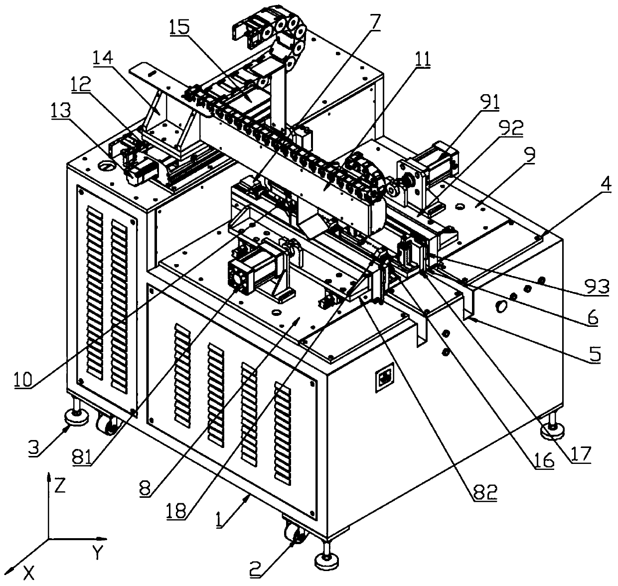
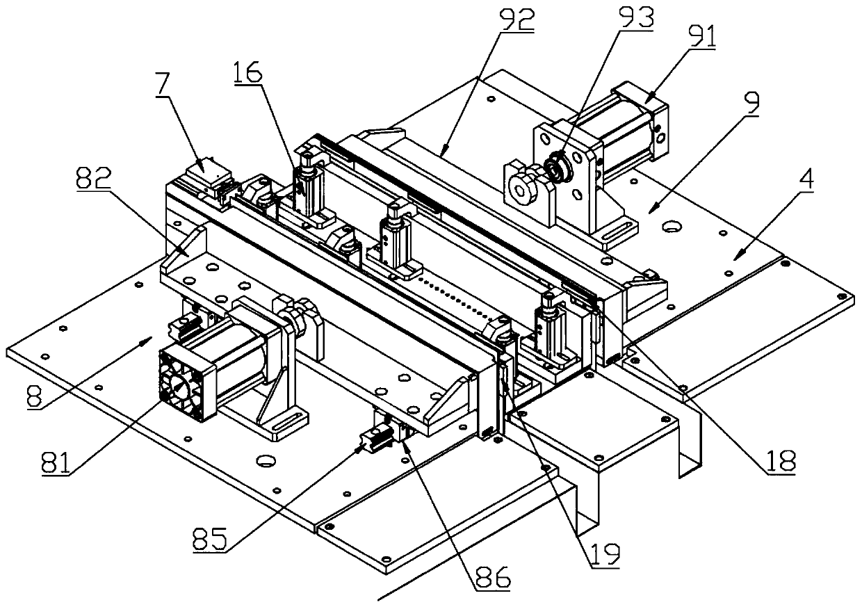
[0024] see figure 1 As shown, a laser automatic welding equipment with sliding guide rails includes a welding equipment box 1, a support plate 4, a left welding tool 8, a right welding tool 9 and a laser welding head 10. The welding equipment box 1 A support plate 4 is installed on the top, and the support plate 4 is divided into left and right double stations for welding, which are the left welding tool 8 and the right welding tool 9 respectively. The left welding tool 8 and the right welding tool 9 are provided with The laser welding head 10 is installed on the XY axis moving frame.

[0025] In order to improve the convenience of moving the welding equipment box 1 and the stability of placement, in the embodiment of the present invention, the four corners of the bottom of the welding equipment box 1 are installed wit...


PUM


Abstract

The invention discloses automatic laser welding equipment with a slide guide rail. The automatic laser welding equipment with the slide guide rail comprises a welding equipment box body, a support plate, a left-side welding fixture, a right-side welding fixture and a laser welding head, wherein the support plate is installed at the top of the welding equipment box body; double stations at the leftside and the right side are formed on the support plate; the left-side welding fixture and the right-side welding fixture are arranged at the double stations at the left side and the right side separately; the laser welding head is arranged above the left-side welding fixture and the right-side welding fixture; and the laser welding head is installed on an XY-axis moving frame. By forming the double stations at the left side and the right side on the welding equipment box body, close and firm contact between an upper part and a lower part which are superposed, of a housing and a support of the product, is ensured; the laser welding head arrives at an initial position of the product and starts to carry out laser welding, the operation is convenient and rapid, machining links for the product are effectively reduced, and the laser welding can be directly carried out on a specific position of the product without the need of drilling; and the problem of bulging of a rivet is avoided afterwelding spraying for the product.

Description

technical field [0001] The invention relates to the technical field of laser welding, in particular to a laser automatic welding device with sliding guide rails. Background technique [0002] Laser welding is an efficient and precise welding method that uses a high-energy-density laser beam as a heat source, and is one of the important aspects of the application of laser material processing technology. The welding process is of the heat conduction type, that is, the surface of the workpiece is heated by laser radiation, and the surface heat diffuses to the interior through heat conduction. By controlling the parameters such as the width, energy, peak power and repetition frequency of the laser pulse, the workpiece is melted to form a specific molten pool. Due to its unique advantages, it has been successfully used in the precision welding of micro and small parts. [0003] Laser welding usually adopts manual welding, and the wages of welding technicians are higher, which in...

Claims


Application Information

Patent Timeline
Patent Type & Authority Applications(China)
IPC IPC(8): B23K26/21B23K26/70B23K37/04
CPCB23K26/21B23K26/702B23K37/0435
Inventor 尚守伟
Owner 佛山市鑫全利数控设备有限公司
Why Eureka
Try Eureka