
Liquid crystal-based adjustable band-stop miniaturized frequency selective surface

A frequency selective surface, band-stop technology, applied in electrical components, antennas, etc., can solve the problems of improved equipment integration, insufficient working resonance frequency wavelength, unfavorable band-stop frequency selection surface stability, etc., to achieve good incident angle stability. The effect of stability, good angle stability

Active Publication Date: 2020-06-09
哈尔滨工大卫星技术有限公司
View PDF5 Cites 0 Cited by
  • Summary
  • Abstract
  • Description
  • Claims
  • Application Information

AI Technical Summary

Problems solved by technology

[0003] In order to solve the problem that the unit size of the existing band-stop frequency selective surface is not small enough compared with the wavelength of the working resonance frequency, which is not conducive to the stability of the band-stop frequency selective surface and the improvement of equipment integration, a liquid crystal-based Miniaturized frequency selective surface with tunable bandstop

Method used


Image

  • Liquid crystal-based adjustable band-stop miniaturized frequency selective surface
  • Liquid crystal-based adjustable band-stop miniaturized frequency selective surface
  • Liquid crystal-based adjustable band-stop miniaturized frequency selective surface

Examples


specific Embodiment approach 1

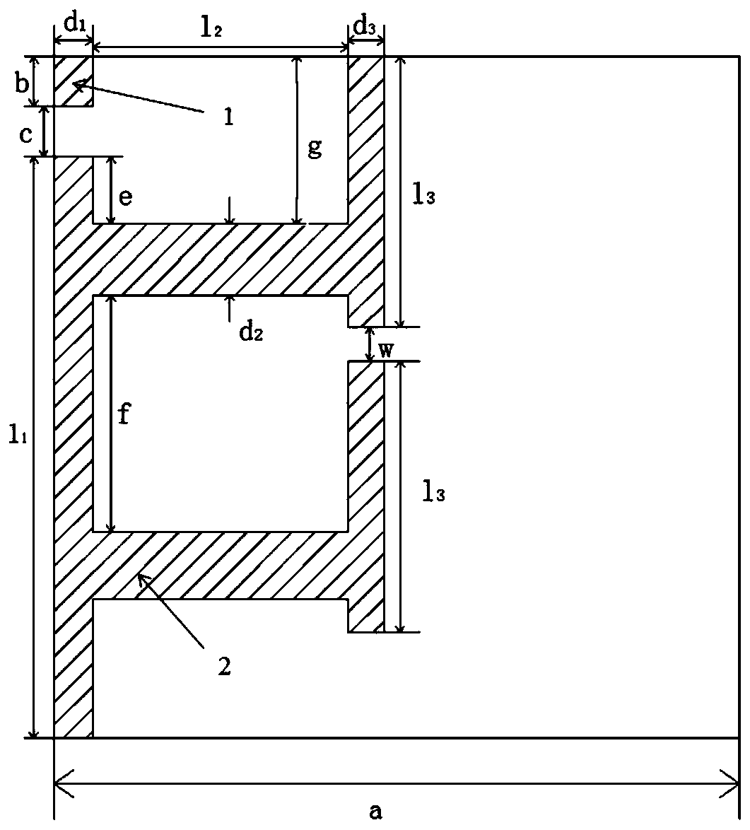
[0031] The selected surface structure of this embodiment is composed of M×N periodically distributed units with a side length of a=2mm, and each unit is sequentially composed of a first dielectric layer, a first metal layer, a second dielectric layer, The second metal layer and the third dielectric layer are laminated. The first dielectric layer, the second dielectric layer and the third dielectric layer are all square structures with a side length of 2 mm. The thickness of the first dielectric layer and the third dielectric layer is 0.1 The relative permittivity ε of mm 1 =4.3, FR-4 material with relative magnetic permeability μ=1. The second dielectric layer is a GT3-23001 liquid crystal material with a thickness of 0.15 mm, a relative permittivity of ε (ε can be adjusted between 2.5 and 3.3), a relative permeability of μ = 1, and an electrical loss tangent of tan δ = 0.0143 .

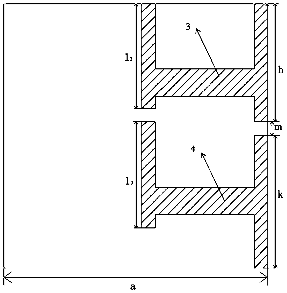
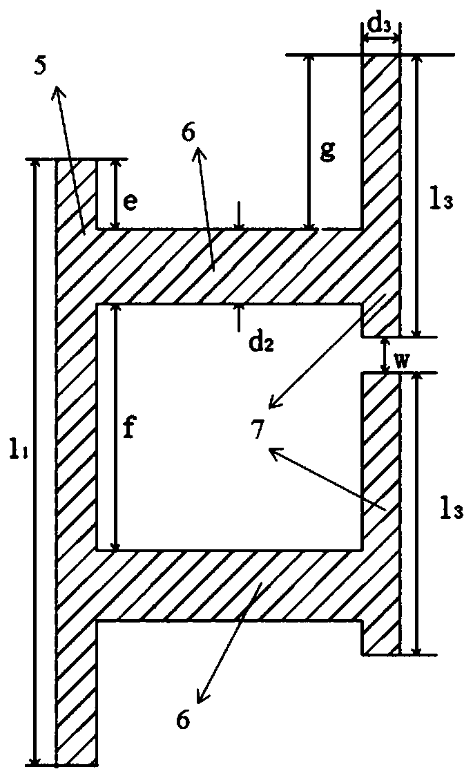
[0032] Such as Figure 1 to Figure 5 As shown, the first metal layer includes structure I1 and...


PUM

PropertyMeasurementUnit
thicknessaaaaaaaaaa
thicknessaaaaaaaaaa
frequencyaaaaaaaaaa

Abstract

The invention discloses a liquid crystal-based adjustable band-stop miniaturized frequency selective surface and belongs to the technical field of microwave filtering. The unit size of an existing band-stop frequency selective surface is not small enough compared with the wavelength of working resonance frequency, and as a result, the improvement of the various stability indexes of the band-stop frequency selective surface and equipment integration degree are not facilitated. With the liquid crystal-based adjustable band-stop miniaturized frequency selective surface adopted, the above problemcan be solved. The liquid crystal-based adjustable band-stop miniaturized frequency selective surface is composed of M*N periodically distributed units; each unit is formed by stacking a first dielectric layer, a first metal layer, a second dielectric layer, a second metal layer and a third dielectric layer in sequence from top to bottom. The liquid crystal-based adjustable band-stop miniaturizedfrequency selective surface is high in miniaturization degree, the size of the liquid crystal-based adjustable band-stop miniaturized frequency selective surface is only equivalent to one eighth of the working resonant frequency; the liquid crystal-based adjustable band-stop miniaturized frequency selective surface has wide -10dB stop band width; the -10dB relative bandwidth of the liquid crystal-based adjustable band-stop miniaturized frequency selective surface is 30% or above; the liquid crystal-based adjustable band-stop miniaturized frequency selective surface has a large 8.04% tuning range; and the liquid crystal-based adjustable band-stop miniaturized frequency selective surface has good incident angle stability.

Description

technical field [0001] The invention relates to a liquid crystal-based adjustable band-resistance miniaturized frequency selective surface, which belongs to the technical field of microwave filtering. Background technique [0002] Liquid crystal materials have the advantages of softness, continuous tuning and low dielectric constant, and have been widely used in various fields in recent years. The loss of liquid crystal material is small in the microwave band, so the liquid crystal material has a good application prospect in the microwave band above 10 GHz. A frequency selective surface is a planar structure that has a frequency selective effect on incident electromagnetic waves. Since the frequency selective surface has frequency selective characteristics for incident electromagnetic waves with different operating frequencies, polarization states, and incident angles, it has a wide range of applications in the field of electromagnetics. For example, it can be used as a rad...

Claims


Application Information

Patent Timeline
Patent Type & Authority Applications(China)
IPC IPC(8): H01Q15/00
CPCH01Q15/0013H01Q15/002H01Q15/0026
Inventor 王鸿宇曲成刚孟繁义
Owner 哈尔滨工大卫星技术有限公司
Learn More