Gas sensing device and sensing method

A gas sensing and sensing technology, applied in the field of sensors

Active Publication Date: 2020-06-09
BEIJING INST OF NANOENERGY & NANOSYST
View PDF7 Cites 4 Cited by
  • Summary
  • Abstract
  • Description
  • Claims
  • Application Information

AI Technical Summary

Problems solved by technology

However, further improving single-layer MoS 2 Sensor sensitivity and response / recovery time remain a big challenge

Method used


Image

  • Gas sensing device and sensing method
  • Gas sensing device and sensing method
  • Gas sensing device and sensing method

Examples


Embodiment Construction

[0024] Specific embodiments of the present invention will be described in detail below in conjunction with the accompanying drawings. It should be understood that the specific embodiments described here are only used to illustrate and explain the present invention, and are not intended to limit the present invention.

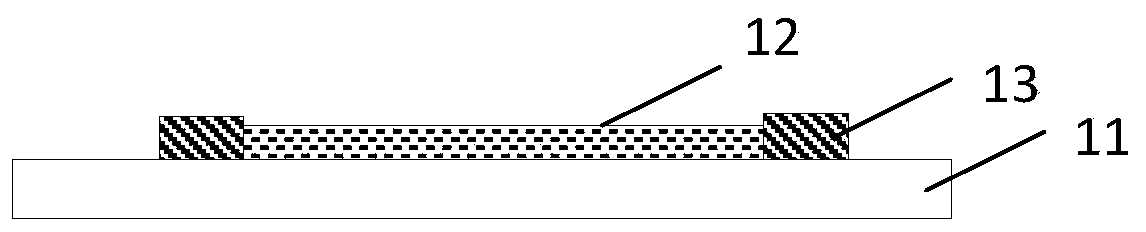
[0025] The typical structure of the gas sensing device provided by the invention is shown in figure 1 , including a flexible sensing component 10, providing a strain component 20 and providing an illumination component 30, wherein the flexible sensing component 10 is used for sensing gas, and the structure is shown in figure 2 , including a flexible substrate 11, the MoS disposed on the substrate 11 2 Sensing layer 12, and set in MoS 2 Electrodes 13 at both ends of the sensing layer 12 .

[0026] Flexible base 11 can adopt flexible material, preferably transparent material, as polyethylene terephthalate (PET), polystyrene (PS), polydimethylsiloxane (PDMS), p...


PUM

PropertyMeasurementUnit
Sensitivityaaaaaaaaaa

Abstract

The invention provides a gas sensing device. The sensing device comprises a flexible sensing component and a strain providing component, wherein the flexible sensing component comprises a flexible substrate, a MoS2 sensing layer arranged on the substrate, and electrodes arranged at two ends of the MoS2 sensing layer, the strain providing part 20 is used for providing strain for a flexible sensingpart 10, an illumination providing component can be further included, and illumination conditions are provided for the flexible sensing component. The sensing device shows higher sensitivity in a flexible sensing part activated by illumination and piezoelectric photoelectronic effects, and the response (recovery) time of the sensing device is sharply shortened.

Description

technical field [0001] The invention relates to the field of sensors, in particular to a gas sensing device and a sensing method. Background technique [0002] NO 2 It is a toxic gas and is considered a key indicator of vehicle emissions, industrial waste gas and environmental monitoring. Development of simple, low-cost and high-efficiency sensors to detect NO 2 Gas is very necessary. In previous work, many nanomaterials have been extensively studied for NO 2 Detection, such as carbon nanotubes and metal oxides with specific structures (eg: ZnO nanowires, TiO 2 Nanotubes and Cu 2 O nanoparticles), the NO 2 Has high sensitivity. [0003] Recently, based on two-dimensional molybdenum sulfide (MoS 2 ) Field-effect transistor (FET) sensors have attracted researchers' interest due to their high response to gas molecules. However, these traditional single bare FET sensors usually require a large external gate bias to achieve higher sensitivity. Especially, for atomically...

Claims


Application Information

Patent Timeline
Patent Type & Authority Applications(China)
IPC IPC(8): G01N27/414
CPCG01N27/4141Y02A50/20
Inventor 郭俊猛翟俊宜
Owner BEIJING INST OF NANOENERGY & NANOSYST
Why Eureka
Try Eureka