A DMD-based coded imaging Raman spectrometer and method

A Raman spectrometer and imaging technology, applied in the optical field, can solve problems such as waste of resources, low utilization rate, and poor accuracy, and achieve the effects of improving detection accuracy, reducing costs, and improving accuracy

Active Publication Date: 2020-11-10
NANJING TECH UNIV
View PDF9 Cites 0 Cited by
  • Summary
  • Abstract
  • Description
  • Claims
  • Application Information

AI Technical Summary

Problems solved by technology

[0004] The invention is used to solve the problems of high price of traditional CCD, poor accuracy of traditional DMD spectrometer, high signal-to-noise ratio, low utilization rate and waste of resources, etc., and proposes a coded imaging Raman spectrometer based on DMD

Method used


Image

  • A DMD-based coded imaging Raman spectrometer and method
  • A DMD-based coded imaging Raman spectrometer and method
  • A DMD-based coded imaging Raman spectrometer and method

Examples


Embodiment Construction

[0046]The present invention will be further elaborated below in conjunction with the accompanying drawings. The following examples are only used to illustrate the technical solutions of the present invention more clearly, but not to limit the protection scope of the present invention.

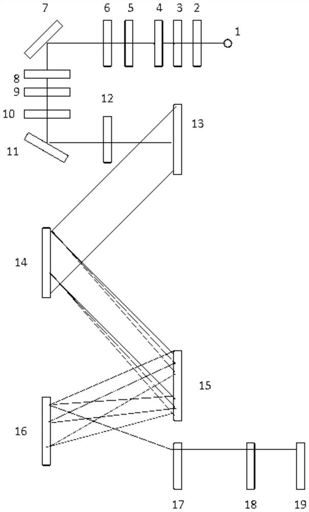
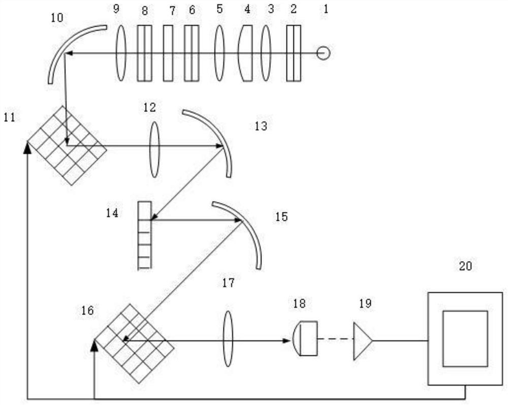
[0047] Such as figure 1 and figure 2 As shown, the light from the laser transmitter 1 irradiates the object 7 to be measured, and the scattered light enters the coating technology mirror 8, and after the coating technology mirror 8 filters light, it is irradiated to the first DMD 11 for selective reflection to the second concave reflection mirror 13, the second concave reflector 13 is reflected to the ruled reflective grating 14, and it is reflected to the third concave reflector 15 after performing spectroscopic processing on the light, and the third concave reflector 15 performs light splitting The light classified into the same wavelength band is gathered together and reflected to the seco...


PUM

PropertyMeasurementUnit
wavelengthaaaaaaaaaa

Abstract

The invention discloses a DMD-based coded imaging Raman spectrometer and a DMD-based coded imaging Raman spectrometer method. A coating technology mirror (8), a first DMD (11), a second concave reflector (13), a reticle type reflecting grating (14), a third concave reflector (15), a second DMD (16), a third convergent lens (17), a photomultiplier (18) and an amplifier (19) are sequentially arranged on a scattered light path after light of the laser emitter (1) is emitted into a to-be-measured object (7). A cambered surface of the third convergent lens (17) faces the second DMD (16), and the other surface of the third convergent lens (17) faces the photomultiplier (18); and the first DMD (11), the second DMD (16), the photomultiplier (18) and the amplifier (19) are connected with a controlterminal. The problems that a traditional CCD is high in price, a traditional DMD spectrograph is poor in accuracy, the utilization rate is low, and resources are wasted are solved, and the good application and popularization value is achieved.

Description

technical field [0001] The invention relates to a coded imaging Raman spectrometer based on DMD, which belongs to the field of optical technology. Background technique [0002] When light is irradiated on a substance, it will be scattered. In addition to the elastic component with the same wavelength as the excitation light, there are components longer and shorter than the wavelength of the excitation light in the scattered light. This phenomenon is collectively called the Raman effect. Information about the composition of a substance can be obtained by analyzing the scattered light spectrum. The Raman spectrometer can be used to detect the composition of the item without touching the item, so the Raman spectrometer is widely used in customs, medicine, geology, etc. [0003] The Raman spectrometer is the basis for the development of spectral analysis instrument technology, and its structure is mainly divided into two parts: Raman spectroscopic acquisition and spectroscopic ...

Claims


Application Information

Patent Timeline
Patent Type & Authority Patents(China)
IPC IPC(8): G01N21/65G01N21/01
CPCG01N21/01G01N21/65
Inventor 王晓荣汪洁张冬华杨红鑫邓哲文
Owner NANJING TECH UNIV
Why Eureka
Try Eureka