Heat exchanger, thermal management system of vehicle and vehicle

A heat management system and heat exchanger technology, applied in the field of heat management systems and vehicles, can solve the problems of high manufacturing and development costs, low pressure resistance, low product generalization rate, etc., and achieve simple manufacturing process and convenient The effect of simple processing and structure

Active Publication Date: 2020-06-09
BYD CO LTD
View PDF9 Cites 4 Cited by
  • Summary
  • Abstract
  • Description
  • Claims
  • Application Information

AI Technical Summary

Problems solved by technology

In order to realize the heat exchange between various heat sources, in related technologies, a plate type multi-media heat exchanger is used. However, the structure of this heat exchanger is formed by stamping and then welding of plates, so it is necessary to design different plates for different products. For stamping dies, the generalization rate of products is very low, and the cost of manufacturing and development is high; moreover, because it must ensure welding reliability and heat exchange efficiency, thicker materials cannot be selected for the thickness of the plate, but the pressure resistance of such a structure not very high

Method used


Image

  • Heat exchanger, thermal management system of vehicle and vehicle
  • Heat exchanger, thermal management system of vehicle and vehicle
  • Heat exchanger, thermal management system of vehicle and vehicle

Examples


Embodiment 1

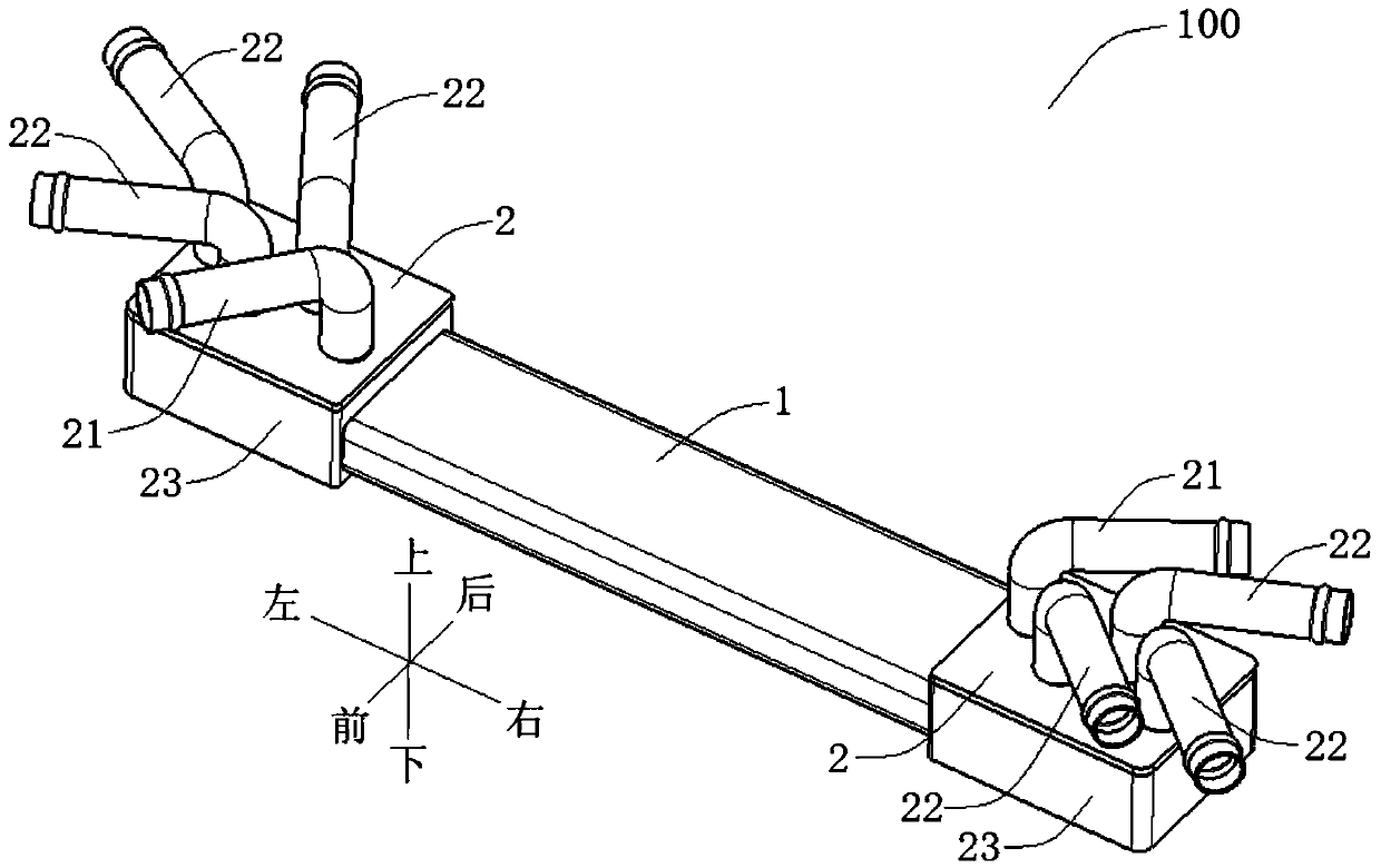
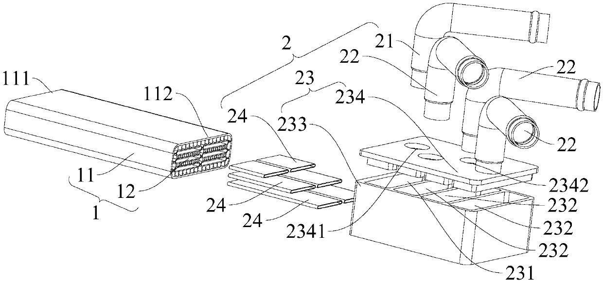
[0099] In this example, if Figure 2-Figure 8 As shown, the heat exchanger 100 includes a body 1 and two joints 2, the body 1 includes a shell 11 and a plurality of passages 12 formed in the shell 11, the shell 11 extends along a straight line, and the cross-sectional outer profile of the shell 11 is roughly formed as a square Structure, the cross-sectional shape of the shell 11 remains unchanged along its axial direction, and the shell 11 is an extruded integral piece; each channel 12 runs through the first end 111 of the shell along the length direction of the shell 11 to the second end of the shell Two ends 112, a plurality of passages 12 include a first passage 121 and three second passages 122, and the three second passages 122 are along the first direction (for example, Image 6 The upper and lower directions in the center) are spaced apart, so that each second passage 122 is surrounded by the first passage 121, so that heat exchange will not occur between different seco...

Embodiment 2

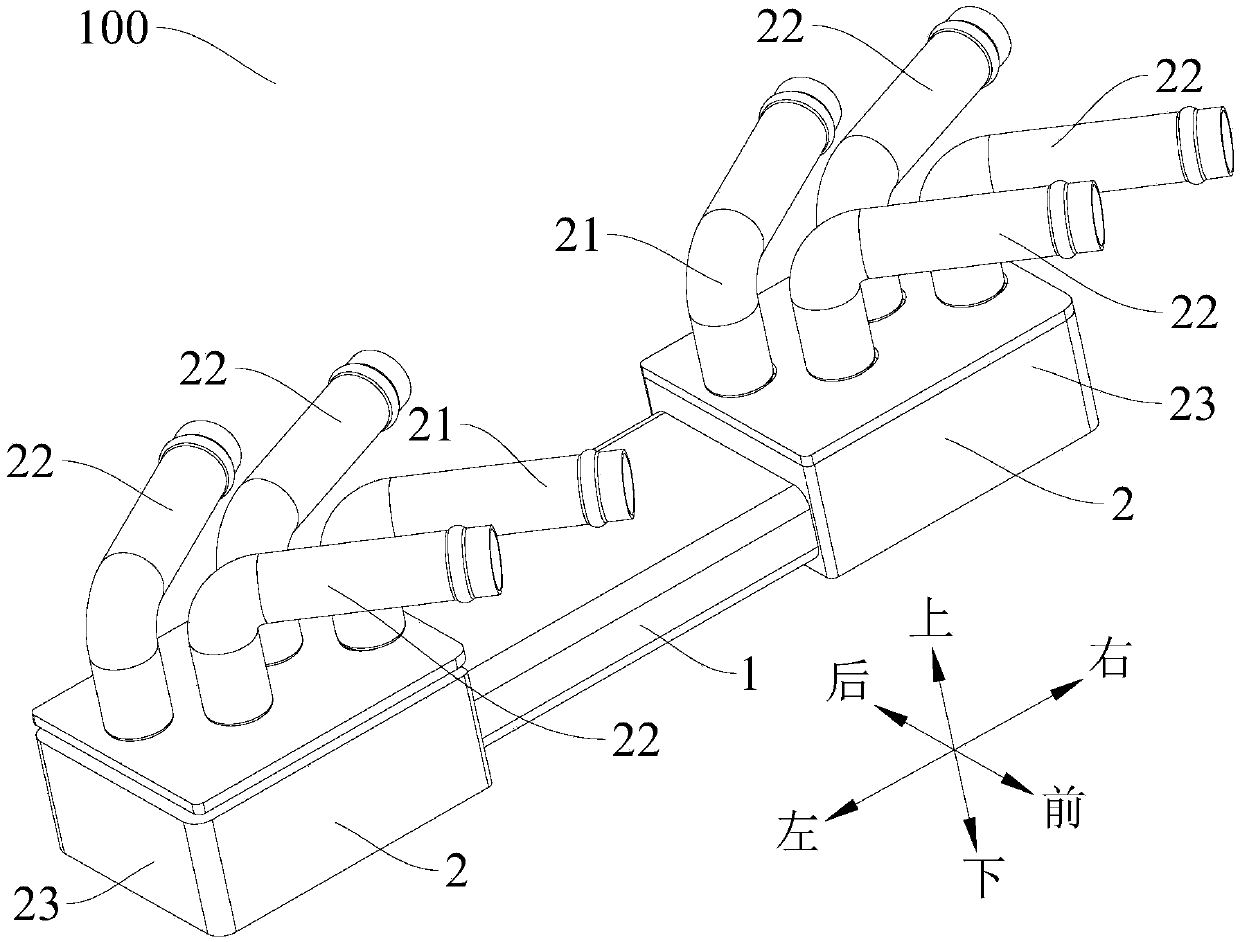
[0106] like figure 1 As shown, the structure of this embodiment is substantially the same as that of Embodiment 1, wherein the same components use the same reference numerals, the difference is that: the free ends of the first connecting pipes 21 of the two joints 2 respectively extend toward directions away from each other , the free ends of the corresponding second connecting pipes 21 of the two connectors 2 respectively extend in directions away from each other.

Embodiment 3

[0108] like Figure 9 As shown, the structure of this embodiment is substantially the same as that of Embodiment 1, wherein the same components use the same reference numerals, the difference is that: the two second sub-channels 1221 of one of the three second channels 12 At least one partition plate 1220 is provided to divide each second sub-channel 1221 into a plurality of sub-flow channels; at this time, the second channel 12 can flow into the refrigerant of the air-conditioning system of the vehicle 300 .

[0109] Refer below Figure 10 and Figure 11 The thermal management system 200 of the vehicle 300 according to the embodiment of the present invention is described in detail with two specific embodiments. It should be understood that the following description is only an illustration rather than a specific limitation to the invention.

[0110] Embodiment one

[0111] In this example, if Figure 10 As shown, the thermal management system 200 includes a heat exchanger...


PUM


Abstract

The invention discloses a heat exchanger, a thermal management system of a vehicle and the vehicle. The heat exchanger comprises a body and two joints; the body comprises a shell and a plurality of channels formed in the shell; each channel penetrates through the shell from a first end of the shell to a second end of the shell; the plurality of channels comprise the first channel and the second channel, and the first channel is arranged around the second channel; the two joints are arranged at the first end and the second end of the shell separately; and each joint comprises a first connectingpipe and a second connecting pipe, wherein the first connecting pipe communicates with the first channel, and the second connecting pipe communicates with the second channel. The heat exchanger is simple in structure, convenient to process and capable of realizing heat exchange among multiple media.

Description

technical field [0001] The invention relates to the technical field of heat exchange, in particular to a heat exchanger, a vehicle heat management system and a vehicle. Background technique [0002] With the continuous development of automobile technology, the structure of automobile power system is becoming more and more complex, and there are more and more temperature sources in the thermal management system. In order to realize the heat exchange between various heat sources, in related technologies, a plate type multi-media heat exchanger is used. However, the structure of this heat exchanger is formed by stamping and then welding of plates, so it is necessary to design different plates for different products. For stamping dies, the generalization rate of products is very low, and the cost of manufacturing and development is high; moreover, because it must ensure welding reliability and heat exchange efficiency, thicker materials cannot be selected for the thickness of th...

Claims


Application Information

Patent Timeline
Patent Type & Authority Applications(China)
IPC IPC(8): F28D7/00F28F9/26B60K11/02
CPCB60K11/02F28D7/0066F28D2021/008F28F9/26
Inventor 胡珂黄梅芳刘丽鑫
Owner BYD CO LTD
Why Eureka
Try Eureka