
Stator apparatus with wiring end disc for an electric motor, and use of the stator apparatus

A technology for motors and stators, applied in electromechanical devices, electric components, electrical components, etc., can solve the problems of troublesome stator unit assembly, limited construction space of contact parts, etc., achieve simple and reliable manufacturability, improve manufacturing quality, and high flexibility degree of effect

Active Publication Date: 2020-06-05
EBM PAPST ST GEORGEN & -
View PDF7 Cites 0 Cited by
  • Summary
  • Abstract
  • Description
  • Claims
  • Application Information

AI Technical Summary

Problems solved by technology

[0010] This concept facilitates an overall space-saving installation of the stator arrangement, but has the disadvantage that the construction space for the contact parts is very limited, especially when the contact parts are implemented as welded hooks
In addition, although the wiring ring can reduce the difficulty of wiring, due to the existence of a large number of single components, the assembly of the stator unit in the manufacturing process is still very troublesome

Method used


Image

  • Stator apparatus with wiring end disc for an electric motor, and use of the stator apparatus
  • Stator apparatus with wiring end disc for an electric motor, and use of the stator apparatus
  • Stator apparatus with wiring end disc for an electric motor, and use of the stator apparatus

Examples


Embodiment Construction

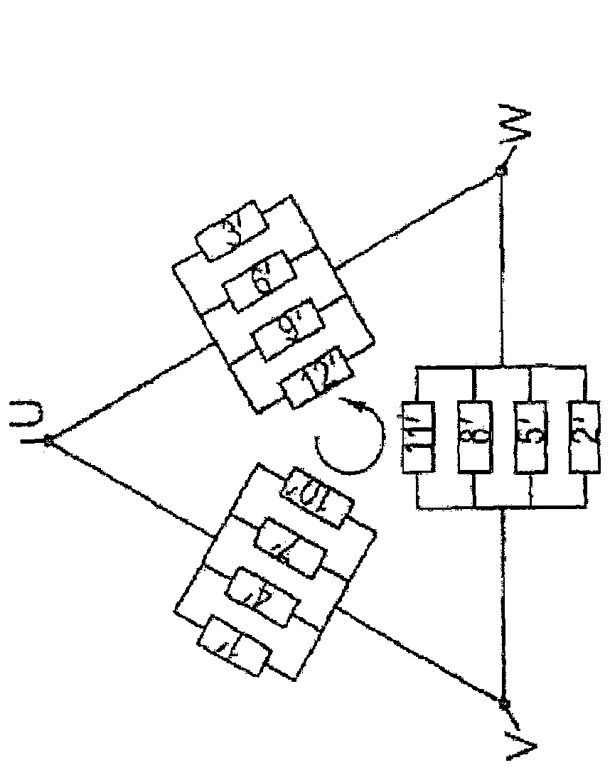
[0037] according to figure 1 and figure 2 As shown in the circuit diagram in , windings 1' to 12' are applied with a three-phase rotating field with phases (terminal polarities) U, V, W, where figure 1 or figure 2 In the manner shown, every four parallel windings of the windings 1' to 12' form a branch of the triangular line shown in the figure, and along the winding carrier 4 ( image 3 ) are nested in the circumferential direction according to their numbers.

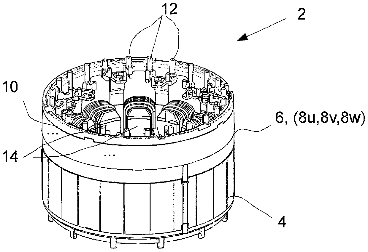
[0038] image 3 The stator arrangement 2 of the invention is shown in a perspective view, according to a first preferred embodiment of the invention, which employs a 12-pole solution for the inner rotor.

[0039] The main components of the stator arrangement 2 consist of a winding carrier 4 for accommodating the windings 1' to 12', a terminal disc 6 with terminal rings 8u, 8v, 8w embedded in an injection-molded encapsulation and on which guide pins 12 are formed The guide disc 10.

[0040] Twelve windings 1' to...


PUM


Abstract

The invention relates to a stator apparatus (2) for an electric motor having a plurality of windings (1' to 12') which are provided on a winding carrier (4), are designed for electromotively interacting with a rotor which is mounted such that it can rotate about a centre axis relative to the winding carrier (4), extend parallel in relation to one another and in relation to the centre axis and arearranged along a profile which is in the form of an arc of a circle and are designed such that they can be individually electrically contacted by winding connections of a winding wire, wherein at least two discs and / or annular, electrically conductively designed wiring rings (8u, 8v, 8w) are associated with the windings (1' to 12') such that they are arranged, in a manner electrically insulated from one another, along an axial direction of the centre axis on the winding carrier (4) such that the winding connections with the same electrical connection polarity (U; V; W) of the windings (1' to 12') are connected to the wiring ring (8u, 8v, 8w), which is associated with this connection polarity (U; V; W), for external common contact-connection in a non-releasable manner by means of welding hooks (20) which are integrally formed with the radially inner side of the wiring ring (8u, 8v, 8w), wherein the wiring rings (8u, 8v, 8w) are integrated into a hollow-cylindrical wiring end disc (6), and in that an annular deflection disc (10) with deflection pins (12), which are arranged distributed around the periphery of the inner side of the deflection disc (10), for deflecting the winding wireis provided on the wiring end disc (6) in the axial direction.

Description

technical field [0001] The invention relates to a stator arrangement for an electric motor according to the preamble of the main claim. Furthermore, the invention relates to the use of such a stator arrangement. Background technique [0002] Stator arrangements of the same type are known from the prior art; such stator arrangements have a winding carrier on which several stator windings, wound with suitable winding wires, are fastened. Depending on the realization principle of a motor realized with such a stator arrangement, these windings are wired or routed in a suitable manner; a typical use of such a general stator arrangement is known to us where the stator arrangement together with the The windings together are constructed and wired to generate a rotating electric field which in turn cooperates with a suitable rotor mounted rotatably about a central axis (either as an outer rotor or an inner rotor). [0003] Using the stator device to generate a three-phase rotating ...

Claims


Application Information

Patent Timeline
IPC IPC(8): H02K3/28H02K3/52H02K5/22
CPCH02K3/28H02K3/522H02K2203/09
Inventor T·威瑟尔C·鲁德尔A·霍诺德H·古德斯-哈梅尼赫
Owner EBM PAPST ST GEORGEN & -
Learn More