Robot joint device

A technology of robot joints and connecting rods, applied in transmission devices, gear transmission devices, manipulators, etc., can solve the problems of reduced durability, limited steering range of motion, and difficulty in precise control, and achieve improved durability, high strength and rigidity. , Improve the effect of precise control

Active Publication Date: 2020-06-05
KOREA UNIV OF TECH & EDUCATION IND UNIV COOPERATION FOUND +1
View PDF7 Cites 1 Cited by
  • Summary
  • Abstract
  • Description
  • Claims
  • Application Information

AI Technical Summary

Problems solved by technology

[0013] However, such a conventional robot joint device has a problem of being difficult to precisely control due to tolerances among a plurality of gears and backlash and friction formed on the gear teeth, and also has problems of reduced durability.
[0014] In addition, it is proposed to realize the 2-degree-of-freedom movement of rotation and steering, so when it is suitable for realizing steering and yaw (yaw) movement, there is a problem of limiting the range of steering movement
[0015] That is, if the existing robot joint device is used to realize turning and yaw (yaw) motion, then there will be contact with the first input body 22 and the second input body 32 during the turning process of the output body 40, thus, it can The steering range is between 0 degrees and 150 degrees, and it is impossible to move in various angle directions

Method used


Image

  • Robot joint device
  • Robot joint device
  • Robot joint device

Examples


Embodiment Construction

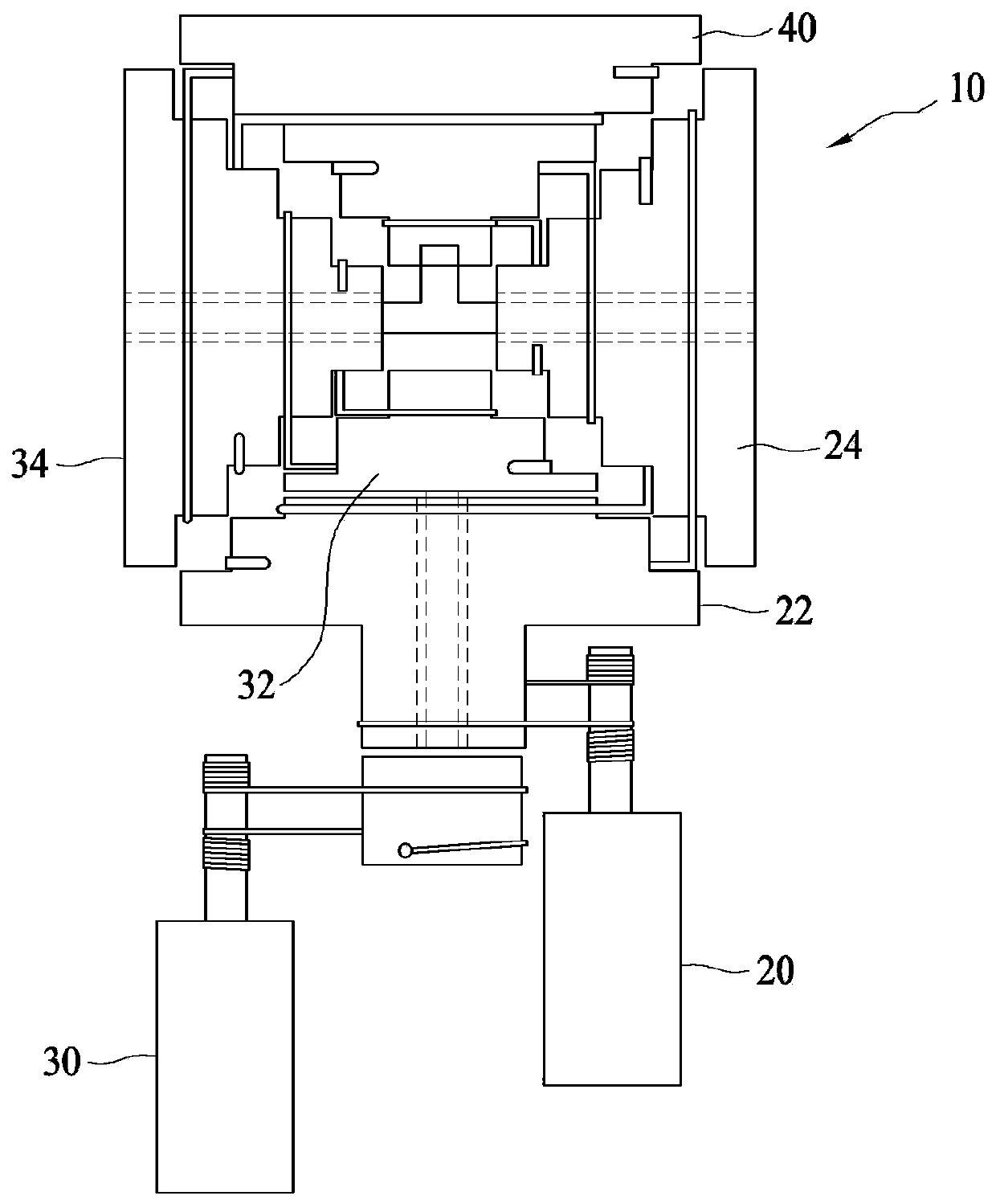
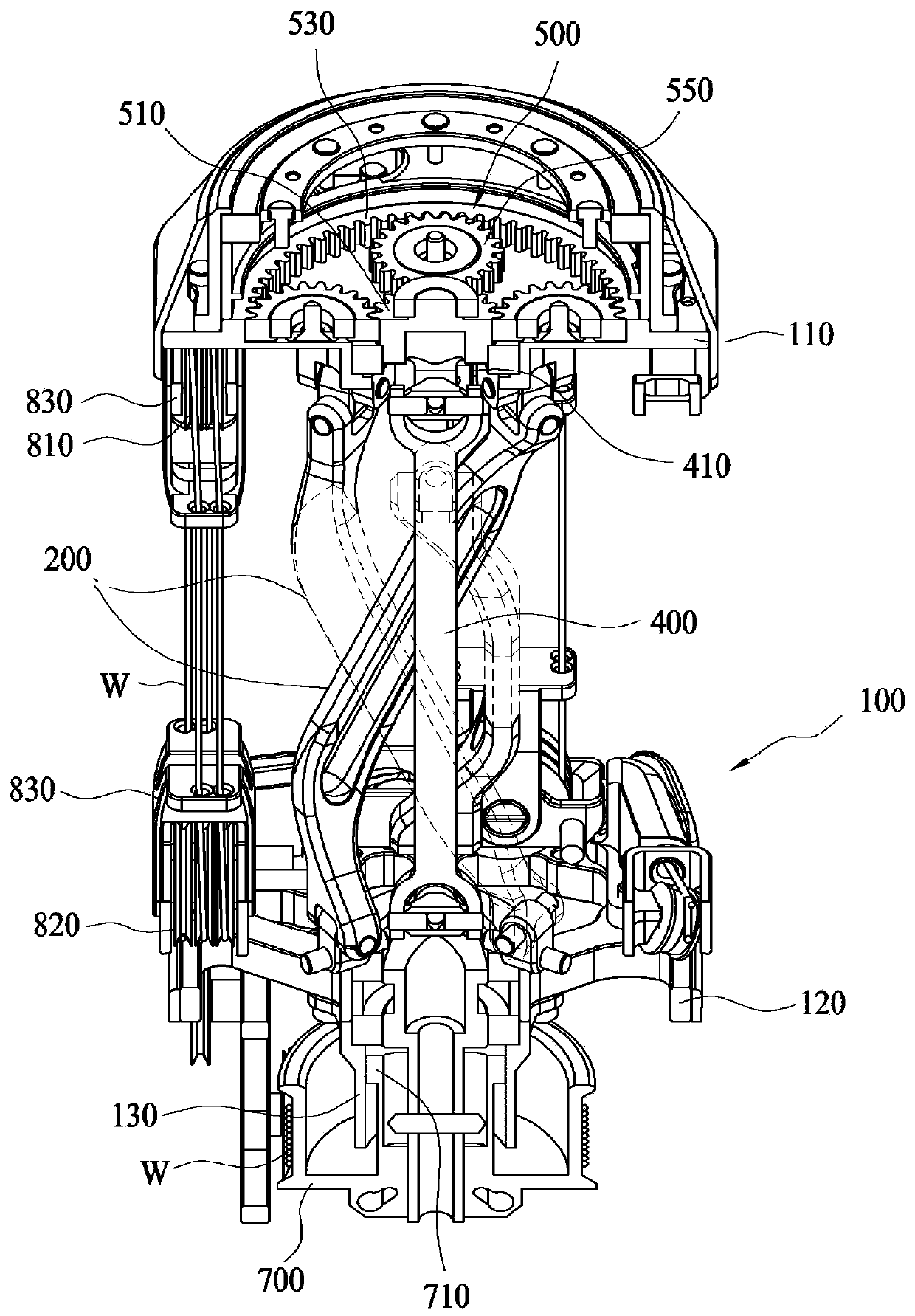
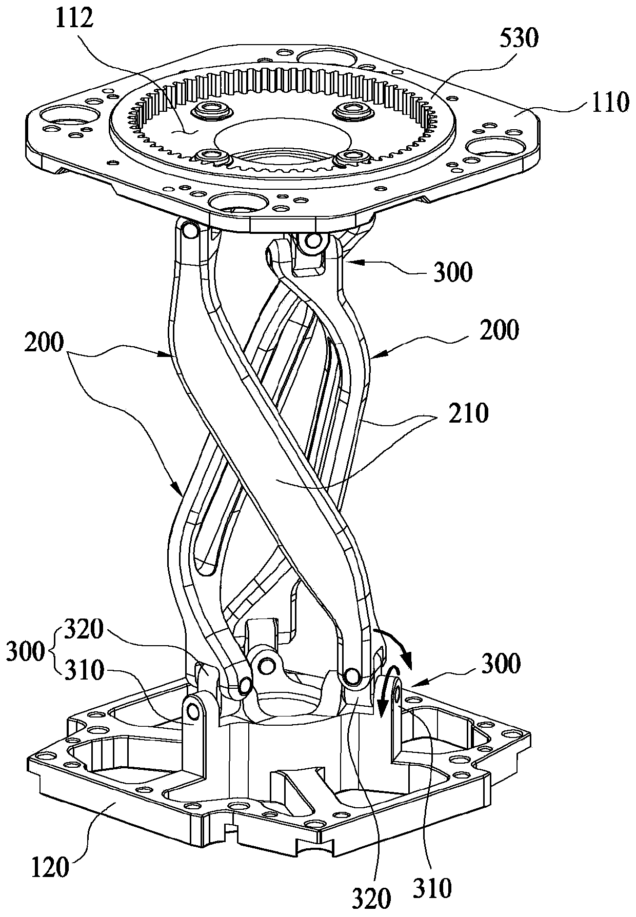
[0045] A robot joint device according to an embodiment of the present invention includes: a first plate and a second plate arranged parallel to each other; a connecting rod connected to the first plate at one end and connected to the second plate at the other end; a connecting member , respectively connected to the two ends of the connecting rod and the first plate and the second plate, so that the connecting rod can adjust the angle and rotation of the first plate and the second plate; the rotating shaft, the two ends are respectively through the first plate and the second plate, and rotatably arranged; the gear reduction part is arranged inside the first plate and connected to one end of the rotating shaft; the pulley is connected to the end of the rotating shaft The other end transmits the driving force to the rotating shaft; and the driving part transmits the driving force to the pulley, the connecting rod is composed of a plurality of one ends and the other ends respective...


PUM


Abstract

The present invention relates to a robot joint device. According to the present invention, a link (200) connects between first and second plates (110, 120) positioned in parallel with each other. A plurality of links (200) are configured and installed such that a plurality of first end portions and a plurality of second end portions thereof are connected to the first and second plates (110, 120),respectively, and connecting points of the first end portions and connecting points of the second end portions constitute polygons, respectively. Both end portions of each link (200) are connected tothe first and second plates (110, 120) by connecting members (300) such that angle and rotation adjustments are possible with regard to the first and second plates (110, 120), respectively. Both endsof a rotating shaft (400) penetrate the first and second plates (110, 120), respectively, and are rotatably installed therein. A gear reduction portion (500) is installed inside the first plate (110)and is connected to the first end of the rotating shaft (400). A pulley (700) is connected to the second end of the rotating shaft (400) so as to transfer driving power to the rotating shaft (400). The pulley (700) receives driving power from a driving portion. The present invention, which has the above-mentioned configuration, is advantageous in that the movement of a human wrist or the like canbe implemented realistically, and precise control is enabled by absence of any problem caused by backlash and friction resulting from conventional gear teeth, thereby improving the durability of the product.

Description

technical field [0001] The present invention relates to a robot joint device. More specifically, it relates to a parallel-type link structure and a rotating shaft capable of rotating with 3 degrees of freedom at the center of the parallel-type link structure to realize various joint angles, and at the same time, it can A robot joint device with improved durability. Background technique [0002] Recently developed robots have joints such as human shoulders, arms, elbows, and wrists, and have various joint angles. Through changes in these joint angles, they can work, move, and exercise. [0003] As a result, robots of various levels, such as robots that share a working space with humans, surgical robots that can easily perform various operations such as laparoscopic surgery, and industrial robots that can perform safe physical contact with humans, will be manufactured. [0004] In this robot there is a robotic joint device to drive the joints. Existing robot joint devices ar...

Claims


Application Information

Patent Timeline
Patent Type & Authority Applications(China)
IPC IPC(8): B25J17/02B25J9/10
CPCF16H1/28B25J9/102B25J9/104B25J17/0266B25J17/0216B25J17/0283
Inventor 金容载金宗仁尹俊锡
Owner KOREA UNIV OF TECH & EDUCATION IND UNIV COOPERATION FOUND
Why Eureka
Try Eureka