
Power distribution cabinet with fireproof and heat dissipation functions

A power distribution cabinet and functional technology, applied in the substation/distribution device shell, electrical components, substation/switch layout details, etc., can solve problems such as short circuit of power distribution cabinet, fire in power distribution cabinet, fire spread, etc., to avoid oxygen Access, simple structure, reasonable design effect

Pending Publication Date: 2020-06-05
安徽千亚电气有限公司
View PDF0 Cites 3 Cited by
  • Summary
  • Abstract
  • Description
  • Claims
  • Application Information

AI Technical Summary

Problems solved by technology

When the power distribution cabinet is used, due to the working environment and operation, it often causes a short circuit or other faults in the power distribution cabinet, resulting in a fire in the power distribution cabinet, and because the existing power distribution cabinets generally only pay more attention to ventilation, resulting in distribution When the electrical cabinet catches fire, it is easy to spread the fire and expand the scope of the fire, which will cause serious losses to the economy and financial resources. Therefore, it is imminent to invent a power distribution cabinet with the function of fire prevention and heat dissipation.

Method used


Image

  • Power distribution cabinet with fireproof and heat dissipation functions

Examples


Embodiment Construction

[0014] The following will clearly and completely describe the technical solutions in the embodiments of the present invention with reference to the accompanying drawings in the embodiments of the present invention. Obviously, the described embodiments are only some, not all, embodiments of the present invention. Based on the embodiments of the present invention, all other embodiments obtained by persons of ordinary skill in the art without making creative efforts belong to the protection scope of the present invention.

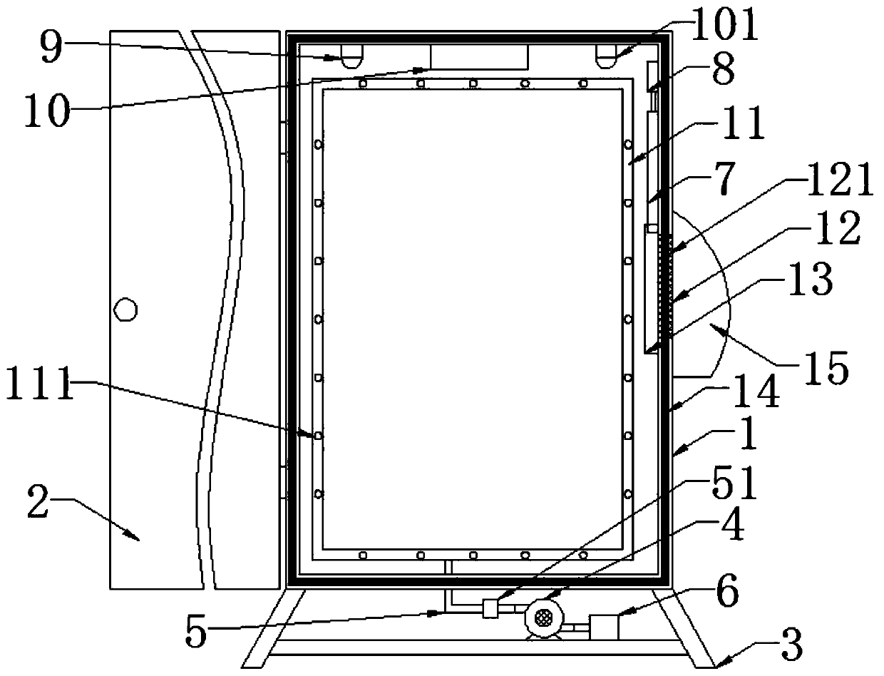
[0015] refer to figure 1 , a power distribution cabinet with fire-proof and heat-dissipating functions, comprising a power distribution cabinet body 1 and a power distribution cabinet door 2 hinged on the power distribution cabinet body 1 , a bracket 3 is installed at the bottom of the power distribution cabinet body 1 .

[0016] An air outlet pipe 11 is installed on the inner wall of the power distribution cabinet body 1, and a number of air outlet holes 111 ...


PUM


Abstract

The invention discloses a power distribution cabinet with fireproof and heat dissipation functions. The power distribution cabinet comprises a power distribution cabinet body. A support is installed at the bottom of the power distribution cabinet body. An air outlet pipe is installed on the inner wall of the power distribution cabinet. A plurality of air outlet holes are formed in the air outlet pipe. A fan is installed on the support. The air outlet end of the fan is connected with the air outlet pipe through a connecting pipe. An air outlet is formed in a side plate of the power distributioncabinet. Guide rails are symmetrically installed on the two sides of the air outlet. A flexible plate is inserted between the guide rails, and an electric cylinder is installed on one side of the flexible plate. The extending end of the electric cylinder is connected with the flexible plate. A temperature sensor, a controller and a smoke sensor are sequentially installed on the inner wall of thetop plate of the power distribution cabinet body from left to right. Compared with the prior art, the power distribution cabinet has the beneficial effects that the power distribution cabinet is simple in structure and reasonable in design; the power distribution cabinet can automatically and quickly discharge heat when the temperature in the power distribution cabinet is too high; and when a fireoccurs in the power distribution cabinet, the controller closes an electromagnetic valve and closes the air outlet, oxygen is prevented from entering the power distribution cabinet, and the fire is automatically extinguished.

Description

technical field [0001] The invention relates to the technical field of power distribution cabinets, in particular to a power distribution cabinet with the function of fire prevention and heat dissipation. Background technique [0002] The power distribution cabinet is a device for receiving power and supplying power to load devices installed at various power users. The power distribution cabinet can monitor, control and protect the power system, and various electrical devices such as switches, transformers, and meters Can be accommodated and used in distribution cabinets. When the power distribution cabinet is used, due to the working environment and operation, it often causes a short circuit or other faults in the power distribution cabinet, resulting in a fire in the power distribution cabinet, and because the existing power distribution cabinets generally only pay more attention to ventilation, resulting in distribution When the electrical cabinet catches fire, it is eas...

Claims


Application Information

Patent Timeline
IPC IPC(8): H02B1/30H02B1/38H02B1/28H02B1/56
CPCH02B1/28H02B1/30H02B1/38H02B1/565
Inventor 张群李可峰李春苗
Owner 安徽千亚电气有限公司
Learn More