Electric brush pressure self-adjusting conductive slip ring structure

A conductive slip ring, brush pressure technology, applied in the direction of circuits, current collectors, electrical components, etc., can solve the problems of long product development, design and finalization cycle, difficulty in meeting the pressure requirements between slip rings, and limited pressure adjustment capabilities. Achieve the effect of improving life and contact reliability, improving shaping efficiency, and reducing installation accuracy

Active Publication Date: 2020-06-05
邢台国泰发电有限责任公司
View PDF10 Cites 1 Cited by
  • Summary
  • Abstract
  • Description
  • Claims
  • Application Information

AI Technical Summary

Problems solved by technology

[0003] Slip rings are components of sliding electrical contacts. The contact pressure of brushes and rings directly affects the life and contact reliability of slip rings. Different application scenarios have different requirements for the reliability and life of slip rings. The brush pressure needs to be precisely designed according to different scenarios. There are mainly the following factors that affect the contact pressure between the brush and the ring: brush material: elastic modulus, cantilever length, brush deformation, brush wire diameter, by changing the Any variable can change the slip ring brush pressure, usually changing the length of the slip ring brush cantilever or adjusting the installation reference plane of the cantilever. The design of various slip rings is not universal, and the change of product size will lead to the need to redesign the matching slip ring , resulting in a long cycle of final product development, design and finalization
[0004] On the other hand, the brush will gradually wear and become shorter during the sliding contact process, and a spring is usually installed to compensate for the pressure loss caused by the shortening of the brush, so that the pressure between the brush and the ring is maintained at an appropriate level. However, during the adjustment process, the elastic force of the spring will gradually decrease, and its pressure adjustment ability is limited, which makes it difficult to meet the requirements for high pressure between slip rings.

Method used


Image

  • Electric brush pressure self-adjusting conductive slip ring structure
  • Electric brush pressure self-adjusting conductive slip ring structure
  • Electric brush pressure self-adjusting conductive slip ring structure

Examples


Embodiment 2

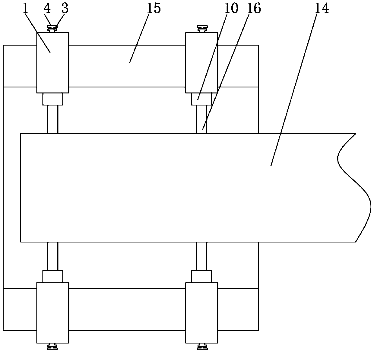
[0026] see Figure 5 , the difference from Embodiment 1 is that the brush 16 is tangent to the outer ring 14, one end of the brush 16 is hinged to the inner ring 15, and the adjustment arm 10 is against the middle of the brush 16, and the adjusting arm 10 is adjusted to the brush 16. The pressure determines the pressure between the brushes 16 and the outer race 14 .

[0027] Principle of work of the present invention and use process:

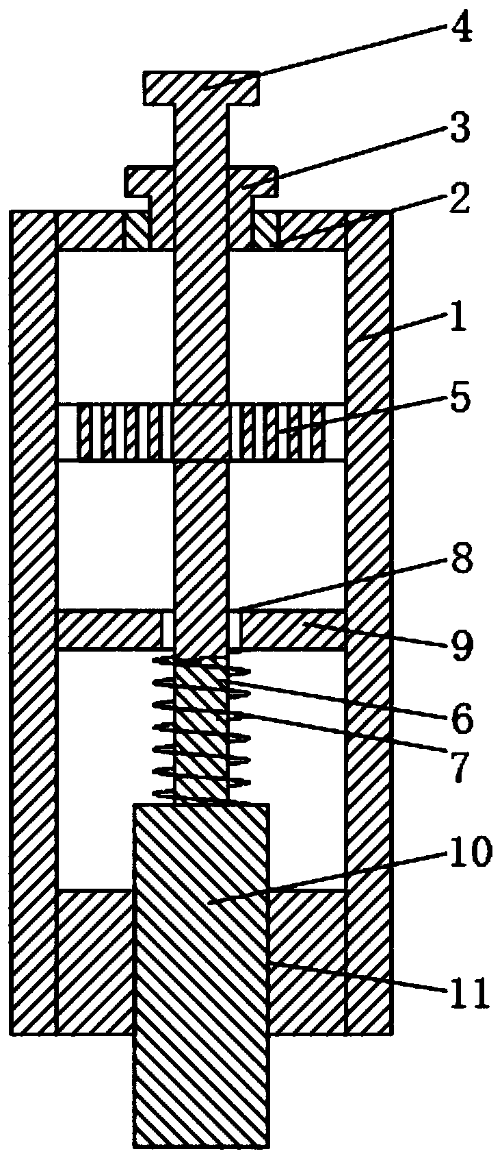
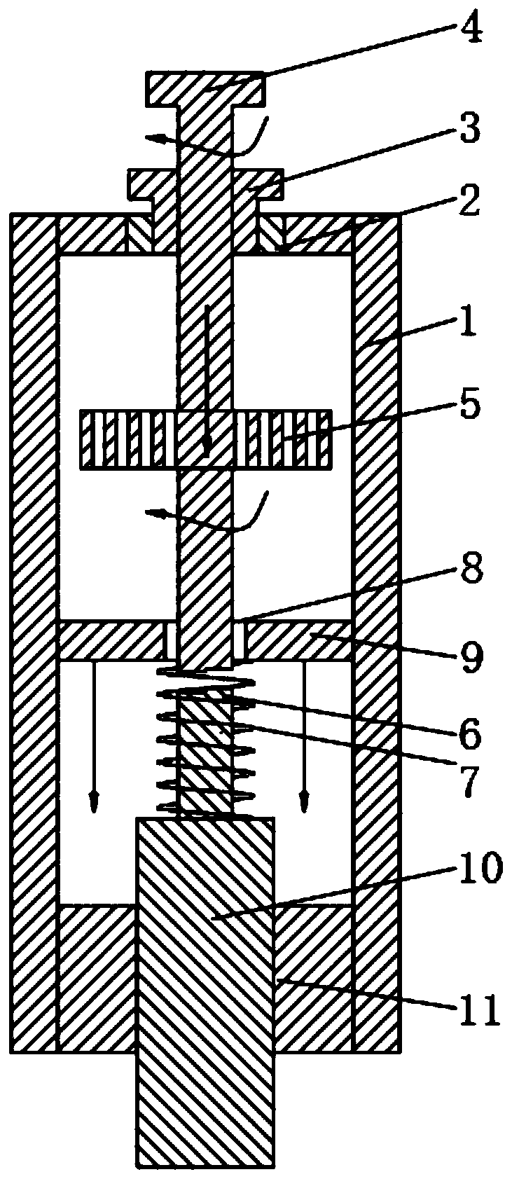
[0028] After the slip ring structure is fixedly installed as in Embodiment 1 or Embodiment 2, the upper end of the adjusting rod 4 is fixed, the threaded sleeve 3 is rotated, and the adjusting rod 4 is screwed into the fixing sleeve 1, and the adjusting rod 4 is compressed to fit the rod 6 and the sliding ring. Groove 7, the initial pressure between the holding brush 16 and the outer ring 14. At this time, since the threaded sleeve 3 can slide up and down in a small range, under the action of the matching rod 6, the adjustment rod 4 and the thr...


PUM


Abstract

The invention relates to the technical field of electrical equipment, and discloses an electric brush pressure self-adjusting conductive slip ring structure. The structure comprises a fixing sleeve, an outer ring and an inner ring, the fixing sleeve is installed on the inner ring, and the inner ring is electrically connected with the outer ring through an electric brush. After the electric brush pressure self-adjusting conductive slip ring structure is mounted and fixed, the pressure between the outer ring and the electric brush can be adjusted by rotating the threaded sleeve, the limitation of the cantilever length and a mounting reference surface is broken through, so the same slip rings are suitable for the design of various electrical products, universality is high, the change of product design is facilitated, and the product research and development efficiency and product shaping efficiency are improved; and meanwhile, after the slip ring is installed, the pressure of the electricbrush can still be measured and adjusted, the requirement for the installation precision is lowered; and, secondly, the pressure change between the outer ring and the electric brush is kept within asmall range all the time under the action of the spring, the contact pressure is guaranteed to be kept within the most appropriate interval, and the higher precision requirement is met.

Description

technical field [0001] The invention relates to the technical field of electrical equipment, in particular to a conductive slip ring structure with self-adjusting brush pressure. Background technique [0002] With the advancement of technology, various automation and intelligent equipment continue to appear, and the movement of equipment is developing in the direction of more degrees of freedom. Rotational movement is a common form of mechanical movement. Continuous rotational movement usually uses slip rings to connect signals and To transmit energy, the slip ring includes a rotating part that moves with the rotating body and a stationary part that is connected to the fixed structure of the equipment. The rotating part and the stationary part are in sliding contact through brushes. [0003] Slip rings are components of sliding electrical contacts. The contact pressure of brushes and rings directly affects the life and contact reliability of slip rings. Different application...

Claims


Application Information

Patent Timeline
Patent Type & Authority Applications(China)
IPC IPC(8): H01R39/64
CPCH01R39/64
Inventor 包平
Owner 邢台国泰发电有限责任公司
Why Eureka
Try Eureka