Antenna and filter connection structure and connection method

A connection structure and filter technology, applied in the direction of the connection of the antenna grounding switch structure and the structure of the radiating element, can solve the problems of difficulty in the filter, occupy a large space, affect the production efficiency, etc., and achieve stable connection mode, convenient disassembly, structure Streamlined effect

Pending Publication Date: 2020-06-05
江苏雳通通讯科技有限公司
View PDF0 Cites 4 Cited by
  • Summary
  • Abstract
  • Description
  • Claims
  • Application Information

AI Technical Summary

Problems solved by technology

This connection method has the following disadvantages: 1) The overall weight of the filter is large, it takes up a lot of space, there are many joint components, and the cost is high; 2) The connection method of the quick connector needs to be assembled in three times, and the operation procedure is cumbersome and error-prone. Affect production efficiency
The disadvantages of this method are: 1) The filter will generate heat during actual operation, and the different materials to be welded have inconsistent thermal expansion coefficients, which will cause many solder joints to be made when the filter cavity and inner conductor are integrally welded on the antenna surface In order to ensure reliable connection between devices and stable antenna performance
Filters with different structures are prone to assembly errors during installation
The direct one-piece welding method makes it difficult to disassemble the incorrectly assembled filter, so the existing connection method will seriously affect the assembly efficiency of the antenna filter

Method used


Image

  • Antenna and filter connection structure and connection method
  • Antenna and filter connection structure and connection method
  • Antenna and filter connection structure and connection method

Examples


Embodiment Construction

[0030] In order to make the purpose and technical solutions of the embodiments of the present invention more clear, the technical solutions of the embodiments of the present invention will be clearly and completely described below in conjunction with the drawings of the embodiments of the present invention. Apparently, the described embodiments are some, not all, embodiments of the present invention. Based on the described embodiments of the present invention, all other embodiments obtained by persons of ordinary skill in the art without creative efforts shall fall within the protection scope of the present invention.

[0031] Those skilled in the art can understand that, unless otherwise defined, all terms (including technical terms and scientific terms) used herein have the same meaning as commonly understood by those of ordinary skill in the art to which this invention belongs. It should also be understood that terms such as those defined in commonly used dictionaries shoul...


PUM


Abstract

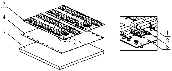
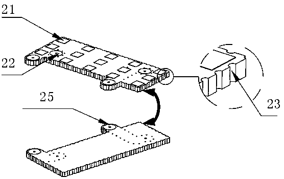
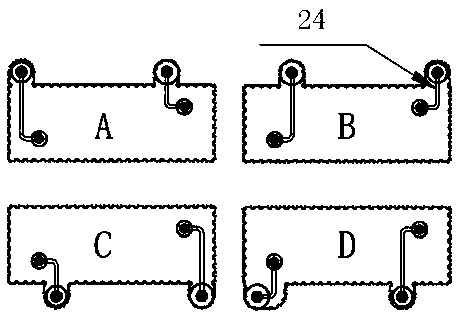
The invention discloses an antenna and filter connection structure and connection method. According to the invention, an adapter plate is arranged between a calibration plate and a filter on the backsurface of the antenna; a signal path between the filter and the antenna calibration plate is formed through the filter connection structure on the adapter plate and a calibration plate connection bonding pad; the connection between the antenna and the filter is realized; the adapter plate is directly attached to the surface of the calibration plate on the back of the antenna in a welding manner without arranging an additional joint; the connecting mode is more stable; the structure is simpler; and disassembly can be convenient.

Description

technical field [0001] The invention relates to the field of antenna connectors, in particular to a connection structure and method for connecting an antenna and a filter. Background technique [0002] With the commercialization of 5G large-scale array antennas, the research and development of 5G antennas has also attracted the attention of major communication companies. At present, 5G antenna components adopt a highly integrated and high-reliability integrated design method, which has a smaller size and reduces feeder loss to make the antenna have better performance. At the same time, the integrated design makes the whole antenna simple and reliable, greatly improving its stability during operation. [0003] In the current antenna design, compared with the traditional 4G antenna, the number of connection channels between the 5G antenna and the filter component increases geometrically. The increase in the number of channels greatly increases the manufacturing cost of 5G an...

Claims


Application Information

Patent Timeline
IPC IPC(8): H01Q1/36H01Q1/38H01Q1/50
CPCH01Q1/36H01Q1/38H01Q1/50
Inventor 崔晓辉吴天昊陆智明
Owner 江苏雳通通讯科技有限公司
Why Eureka
Try Eureka