
Electromagnetic non-line-of-sight imaging method based on time reversal and compressed sensing

A technology of compressed sensing and imaging methods, which is applied to circuits, antennas, electrical components, etc., to achieve strong expansion capabilities, improve signal strength and detection signal-to-noise ratio in occluded areas, and achieve the effect of low complexity

Active Publication Date: 2020-06-05
ZHEJIANG UNIV
View PDF20 Cites 8 Cited by
  • Summary
  • Abstract
  • Description
  • Claims
  • Application Information

AI Technical Summary

Problems solved by technology

[0004] The purpose of the present invention is to overcome the deficiencies and defects in the prior art for the detection of targets in shielded areas where electromagnetic waves cannot penetrate, such as metal objects and high-loss media, and propose a new type of electromagnetic sensing based on time reversal and compressed sensing. The non-line-of-sight imaging method can effectively gather target signals in occluded areas in high-scattering environments, suppress target multipath clutter, and improve imaging accuracy

Method used


Image

  • Electromagnetic non-line-of-sight imaging method based on time reversal and compressed sensing
  • Electromagnetic non-line-of-sight imaging method based on time reversal and compressed sensing
  • Electromagnetic non-line-of-sight imaging method based on time reversal and compressed sensing

Examples


Embodiment Construction

[0064] The present invention will be further described and illustrated below in conjunction with accompanying drawing and example: this example is based on the premise of the technical solution of the present invention, has provided specific implementation and operation process, and the protection scope of the present invention includes but not limited to following example.

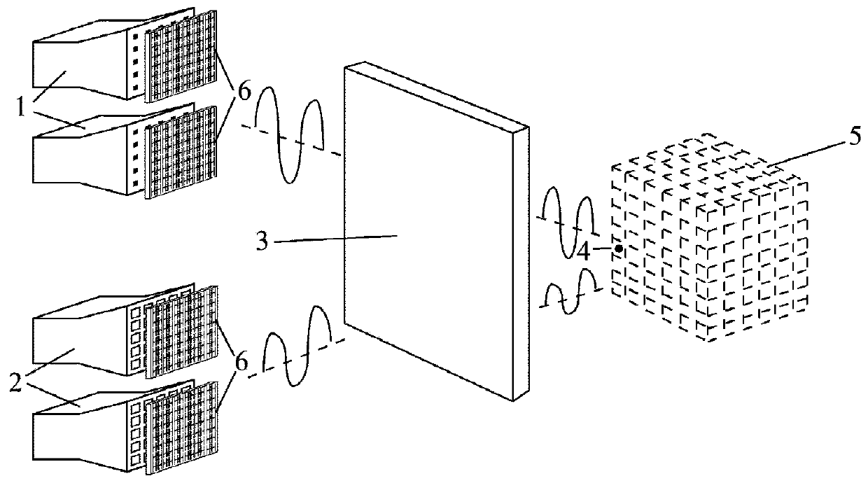
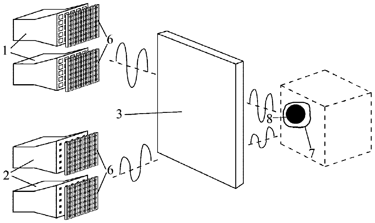
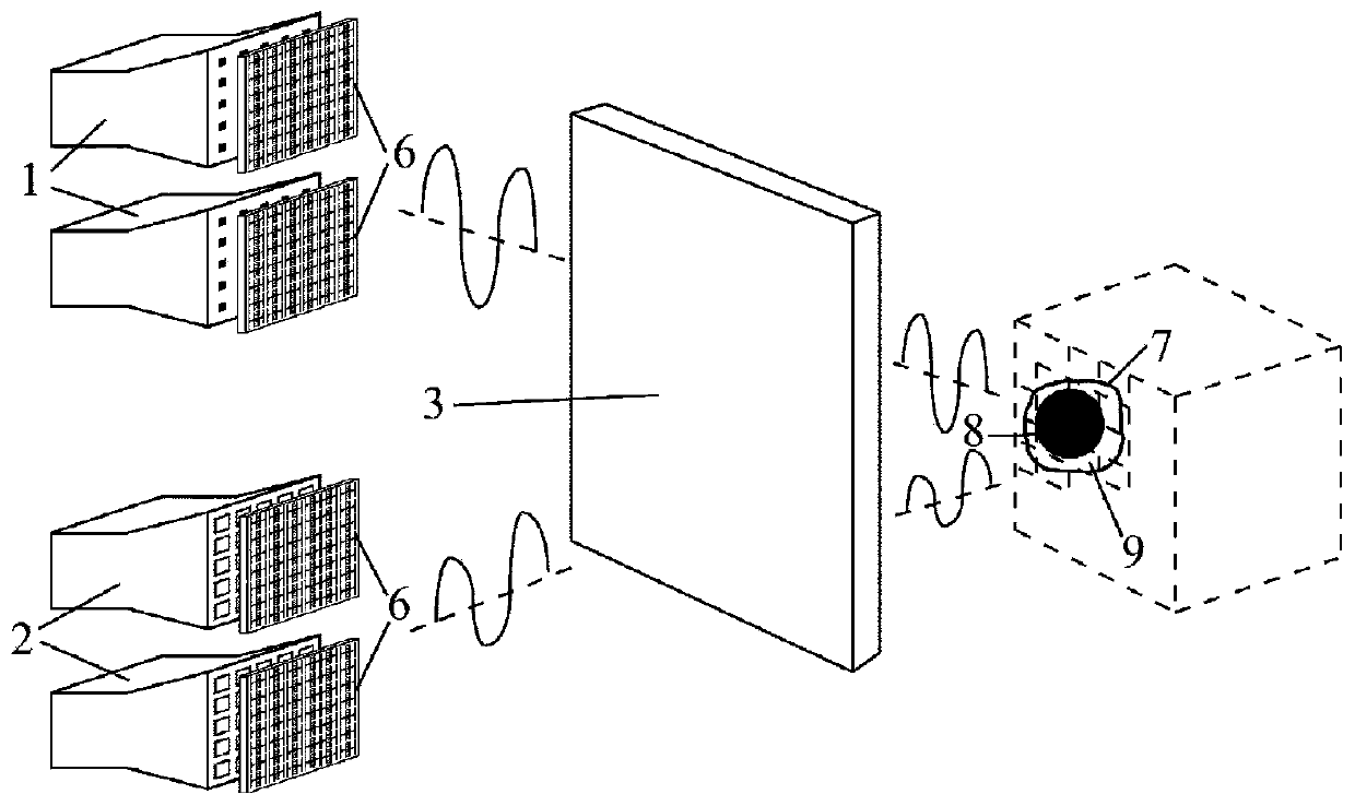
[0065] Such as Figure 1-Figure 3 As shown, the target area V and the antenna array 1 in the transmitting mode / antenna array 2 in the receiving mode are respectively located on two sides of a wall / metal structure 3 that electromagnetic waves cannot penetrate.

[0066] Such as Figure 4 As shown, the antenna array 1 that adopts the transmitting mode includes a transmitting antenna array and an active metasurface radome, and the transmitting antenna array is formed by a plurality of transmitting antenna units 11 arranged in an array, and the transmitting antenna unit 11 is a square metal sheet structure, A ...


PUM


Abstract

The invention discloses an electromagnetic non-line-of-sight imaging method based on time reversal and compressed sensing. An electromagnetic signal passively scattered by a target behind a shieldingobject is received through an antenna, contour imaging of the target is achieved through compressed sensing, the signal-to-noise ratio of the target electromagnetic signal is increased through time reversal for a contour area, and the purpose of staring to detect a non-sight target is achieved. By transmitting a plurality of random radiation signals through active metasurface modulation, and carrying out compressed sensing calculation imaging after receiving, the number of targets in a shielding region and a contour region is judged; for the target contour area, the amplitudes and phase differences of signals obtained at different positions are further adjusted through the active metasurface, and focusing and scanning of electromagnetic signals at different positions behind the shielding object are achieved. According to the invention, a wall body where an electromagnetic signal cannot penetrate and a target in a non-closed scene behind a metal structure can be detected, the detectioncapability of traditional detection and imaging radars is expanded, and the method has a wide application prospect in civil and military fields such as unmanned driving, medical imaging and complex environment radar detection.

Description

technical field [0001] The invention belongs to the technical field of microwave imaging, in particular to an electromagnetic non-line-of-sight imaging method based on time reversal and compressed sensing. Background technique [0002] Electromagnetic target detection has always been an important research direction in academic and engineering fields. It allows unmanned vehicles and intelligent robots to effectively detect and avoid obstacles in complex environments, improving their safety and reliability. During detection, the signal emitted by the electromagnetic wave source is affected by the target, resulting in a change in the received signal, which can be used to judge the characteristics of the target. Reflection, scattering and refraction are common physical processes that affect the propagation of electromagnetic and light waves. When the target is blocked by obstacles, the microwave band that can penetrate obstacles or the low frequency band that can diffract obst...

Claims


Application Information

Patent Timeline
IPC IPC(8): G01S13/89G01S13/88G01S13/93G01S13/931G01S7/03H01Q21/00
CPCG01S13/89G01S13/887G01S13/881G01S13/93G01S13/931G01S7/03H01Q21/00H01Q3/46H01Q15/002H01Q21/06H01Q13/02G01S7/4082H01Q1/40
Inventor 皇甫江涛魏路松汤之仪
Owner ZHEJIANG UNIV
Learn More