Seamless welding device and method for plastic floors

A technology of seamless welding and plastic flooring, applied in metal processing and other fields, can solve problems such as low operating efficiency and high work intensity of workers

Active Publication Date: 2020-06-05
ZHEJIANG TIANZHEN BAMBOO & WOOD DEV
View PDF5 Cites 2 Cited by
  • Summary
  • Abstract
  • Description
  • Claims
  • Application Information

AI Technical Summary

Problems solved by technology

PVC flooring is widely used in all aspects of home and business because of its rich patterns and colors; after laying plastic flooring, it is necessary to weld the joints between two pieces of plastic flooring. Most of the existing welding methods are first through workers Holding a welding torch, squatting for welding, after the weld is solidified, and then cutting off the protruding part with a hand-held cutter, not only the overall operating efficiency is low, but also the work intensity of the workers is high

Method used


Image

  • Seamless welding device and method for plastic floors
  • Seamless welding device and method for plastic floors
  • Seamless welding device and method for plastic floors

Examples


specific Embodiment approach 1

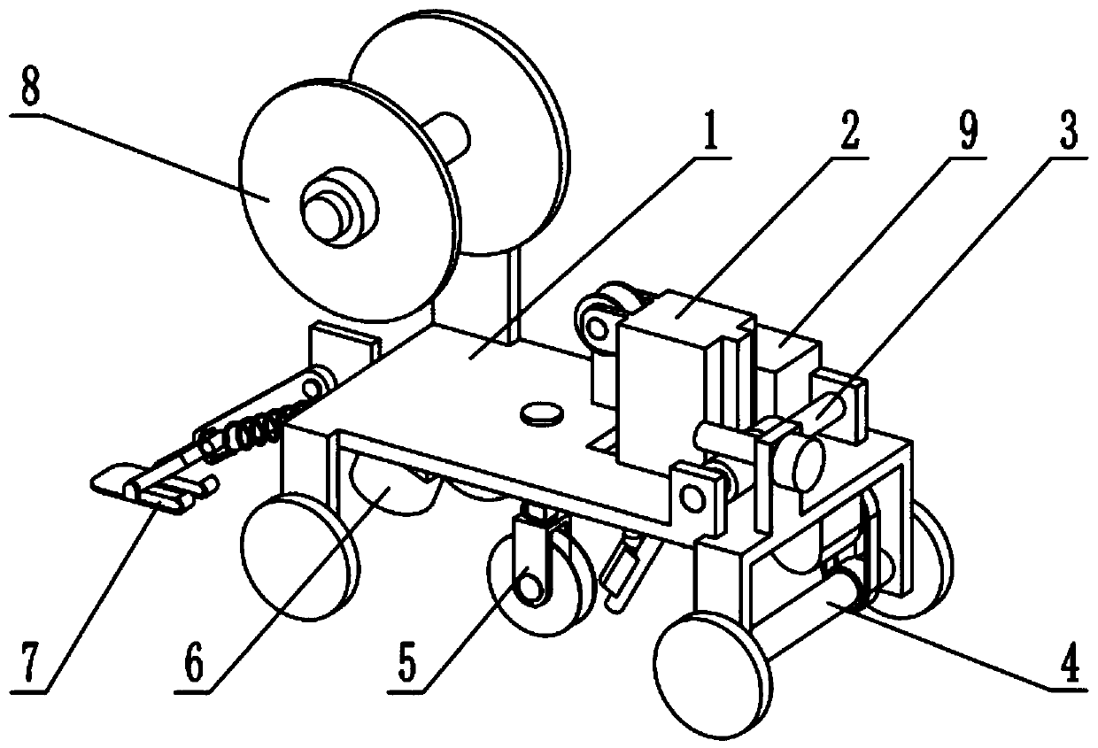
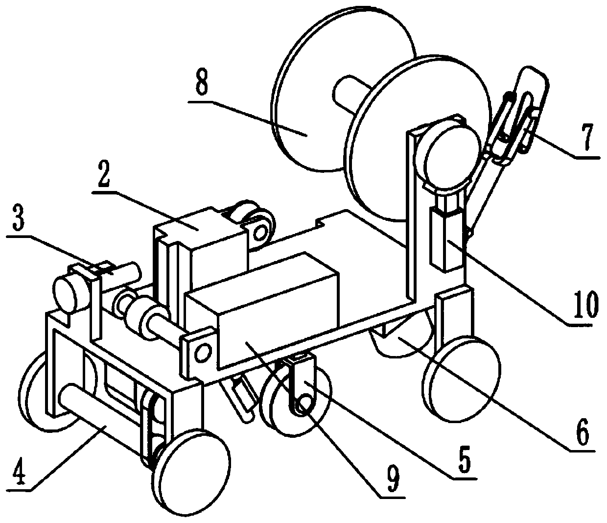
[0034] Such as Figure 1-11As shown, a plastic floor seamless welding device includes a moving frame 1, a welding part 2, a lifting control mechanism 3, a moving mechanism 4, an electrode pressing mechanism 5, a fan 6, a cutter mechanism 7, an electrode installation mechanism 8, a power supply 9 and a brake mechanism 10, the welding part 2 is slidably connected to the moving frame 1, the lifting control mechanism 3 is rotatably connected to the moving frame 1 and connected to the welding part 2, and the moving mechanism 4 is connected to The front end of the mobile frame 1, the electrode pressing mechanism 5 is slidably connected to the mobile frame 1, the electrode pressing mechanism 5 is located directly behind the weldment 2, and the fan 6 is fixedly connected to the lower end of the mobile frame 1. 6 is located directly behind the electrode pressing mechanism 5, the cutter mechanism 7 is connected to the rear end of the mobile frame 1, the cutter mechanism 7 is located dir...

specific Embodiment approach 2

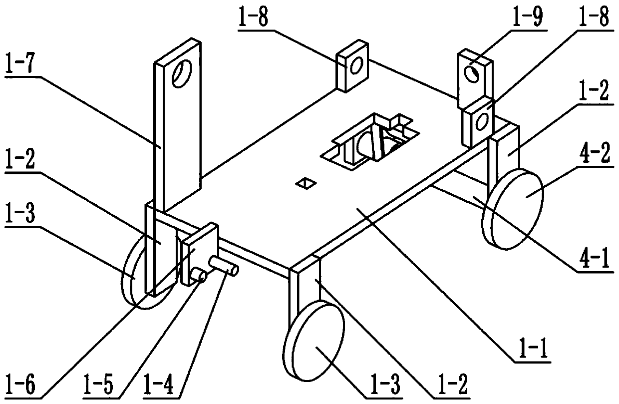
[0037] Such as Figure 1-11 As shown, the mobile frame 1 includes a main board 1-1, a leg plate 1-2, a moving wheel I 1-3, a tension spring connection pin 1-4, a fixed pin 1-5, a fixed plate 1-6, and a support plate 1-7. The mounting plate 1-8 and the mounting seat 1-9, the four corners of the main board 1-1 are welded and fixed with the outrigger plate 1-2, and the two outrigger plates 1-2 at the rear end are connected by bearing rotation There are movable wheels Ⅰ1-3, fixed plate 1-6 is welded and fixed on the rear end of main board 1-1, extension spring connecting pin 1-4 and fixed pin 1-5 are welded and fixed on fixed plate 1-6, and supporting plate 1 -7 is welded and fixed on the upper end surface of the mainboard 1-1 rear end, and the mounting plate 1-8 is provided with two, and the two mounting plates 1-8 are all welded and fixed on the upper end surface of the front end of the mainboard 1-1, and the mounting seat 1- 9 is welded and fixed on the front end of the mainbo...

specific Embodiment approach 3

[0040] Such as Figure 1-11 As shown, the weldment 2 includes a welding torch 2-1, a preheating pipe 2-2, a connecting plate 2-3, a guide wheel 2-4 and a rack 2-5, and the preheating pipe 2-2 is fixedly connected to the welding torch On the torch head of 2-1, two connecting plates 2-3 are provided, and the two connecting plates 2-3 are all fixedly connected to the rear end of the welding torch 2-1, and the guide wheel 2-4 is rotatably connected to the two connecting plates 2 Between -3, the rack 2-5 is fixedly connected to the front end of the welding torch 2-1, the welding torch 2-1 is slidably connected to the main board 1-1, and the welding torch 2-1 is connected to the power supply 9 through a wire and a switch;

[0041] The guide wheel 2-4 on the welding torch 2-1 can guide the electrode that falls off on the electrode roll in the preheating pipe 2-2 in a regular manner, so as to improve the preheating efficiency.


PUM


Abstract

The invention relates to the field of floor welding, in particular to a seamless welding device and method for plastic floors. The device comprises a movable rack, a welding part, a lifting control mechanism, a moving mechanism, a welding rod pressing mechanism, a fan, a cutter mechanism, a welding rod mounting mechanism, a power supply and a brake mechanism, wherein by means of the welding rod mounting mechanism and the brake mechanism, a welding rod coil is convenient to fix, and meanwhile, the condition that welding use is affected by the falling off of a welding rod is prevented; the preheated welding rod is pressed in a welding groove by the welding rod pressing mechanism, the welding rod is prevented from being falsely connected with the welding groove, the welding seam quality is improved, and the device performs continuous welding as well; a welding seam is blown by the fan, welding seam solidification is accelerated, and the higher part of the welding seam is cut by a cutter blade conveniently; and by means of the lifting control mechanism, height of the welding part can be adjusted, and an end of a welding gun can be protected while welding is facilitated. According to the device and the method, working efficiency can be improved, and working intensity of workers is reduced.

Description

technical field [0001] The invention relates to the field of floor welding, in particular to a plastic floor seamless welding device and method. Background technique [0002] Plastic floor is another name for PVC floor. The main component is polyvinyl chloride material. PVC flooring can be made into two types, one is homogeneous and transparent, that is, the pattern material from the bottom to the surface is the same, and the other is composite, that is, the top layer The first layer is a pure PVC transparent layer, with a printing layer and a foaming layer underneath. PVC flooring is widely used in all aspects of home and business because of its rich patterns and colors; after laying plastic flooring, it is necessary to weld the joints between two pieces of plastic flooring. Most of the existing welding methods are first through workers. Holding a welding torch, squatting for welding, and cutting off the protruding part with a hand-held cutter after the weld is solidified...

Claims


Application Information

Patent Timeline
IPC IPC(8): B29C65/02B29C37/00B29C35/16B26D1/02
CPCB29C65/02B29C66/0326B29C66/431B29C66/87B29C35/16B26D1/02B29C2035/1658
Inventor 赵吉
Owner ZHEJIANG TIANZHEN BAMBOO & WOOD DEV
Why Eureka
Try Eureka