Concrete prefabricated part machining device and machining method
A technology of prefabricated components and processing devices, which can be used in the manufacture of tools, mold auxiliary parts, ceramic molding machines, etc., and can solve problems such as inability to expand holes.
- Summary
- Abstract
- Description
- Claims
- Application Information
AI Technical Summary
Problems solved by technology
Method used
Image
Examples
specific Embodiment approach 1
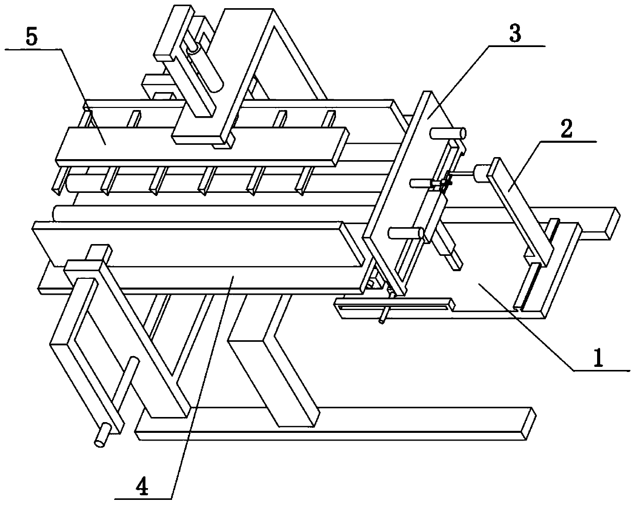
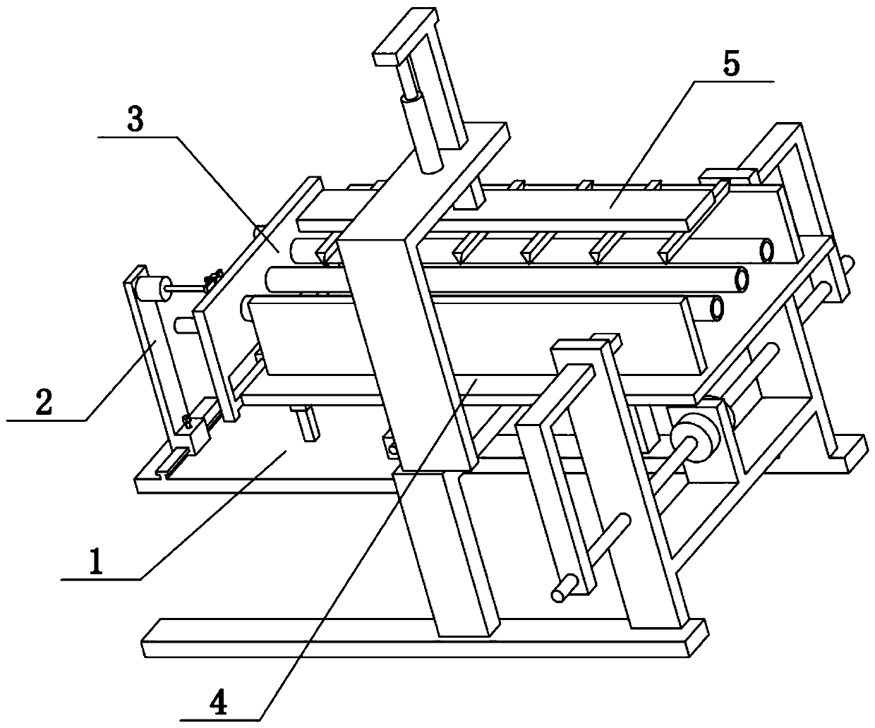
[0033] Combine below Figure 1-9 Describe this embodiment, the present invention relates to the field of concrete prefabricated components processing, more specifically a concrete prefabricated component processing device and processing method, including motor II202, rotating shaft 203, inserting shaft 205, circumferential rotating rod 206, side plate 3, Cylinder 301, hollow round rod 302, vertical column 303, vertical sleeve 304, fixed sleeve 305 and slide rail bar 306, the present invention can process hollow hole in the concrete prefabricated member, and hollow hole can expand as required, and hollow hole can play To the role of material saving and sound insulation.
[0034]A plurality of hollow round rods 302 are evenly distributed on the left side of the side plate 3, the spacing between the plurality of hollow round rods 302 is equal, the plurality of hollow round rods 302 are at the same height, and the right side of the side plate 3 is fixedly connected with a round T...
specific Embodiment approach 2
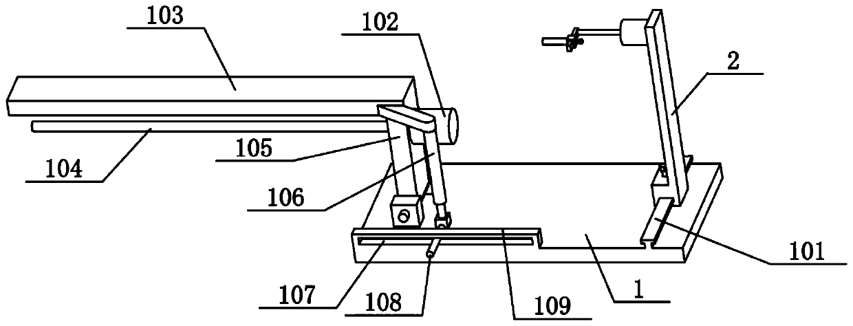
[0036] Combine below Figure 1-9 Illustrate the present embodiment, described concrete prefabricated component processing device also comprises flat plate 1, slide rail 101, motor bracket 2, fastening screw 1201 and sliding sleeve 204, the right end of flat plate 1 is provided with the slide rail 101 of front and rear direction, motor bracket 2 The lower part of the motor is slidably connected to the slide rail 101, the lower part of the motor support 2 is threadedly connected with a fastening screw I201, the fastening screw I201 is pushed on the slide rail 101, the motor II202 is fixedly connected to the upper part of the motor support 2, and the insertion shaft 205 The right end is fixedly connected with a sliding sleeve 204, and the sliding sleeve 204 is slidably connected on the circumferential rotating rod 206, and the sliding sleeve 204 is threadedly connected with a fastening screw I201, and the fastening screw I201 is pushed on the peripheral rotating rod 206. The slid...
specific Embodiment approach 3
[0038] Combine below Figure 1-9 To illustrate this embodiment, the prefabricated concrete component processing device also includes a supporting plate 4 and a splint 401, the front and rear sides of the supporting plate 4 are provided with splints 401, a plurality of hollow round rods 302 are located on the upper side of the supporting plate 4, and a plurality of The hollow rod 302 is located between the two splints 401 . When in use, concrete is placed on the upper side of the supporting plate 4, and the front and rear sides of the concrete are respectively blocked by two splints 401, and the concrete is paved to a certain thickness to form a concrete prefabricated component. A plurality of hollow round rods 302 prop up a plurality of hollow holes in the concrete.
PUM
 Abstract
Description
Claims
Application Information
 - R&D
- Intellectual Property
- Life Sciences
- Materials
- Tech Scout
- Unparalleled Data Quality
- Higher Quality Content
- 60% Fewer Hallucinations
Browse by: Latest US Patents, China's latest patents, Technical Efficacy Thesaurus, Application Domain, Technology Topic, Popular Technical Reports.
© 2025 PatSnap. All rights reserved.Legal|Privacy policy|Modern Slavery Act Transparency Statement|Sitemap|About US| Contact US: help@patsnap.com


