storage table

A technology for storage tables and storage boards, applied in tool storage devices, manufacturing tools, etc., can solve problems such as low efficiency and difficulties

Active Publication Date: 2020-12-15
安庆中巨机电科技有限公司
View PDF6 Cites 0 Cited by
  • Summary
  • Abstract
  • Description
  • Claims
  • Application Information

AI Technical Summary

Problems solved by technology

The coupler box body is made of aluminum alloy. After the box body is made, it needs to be painted. In the actual painting operation, the outer surface of the installation box a where the wiring hole a1 and the wiring point a2 are located is not painted. operation to avoid the influence of later paint on the electrical conductivity of the coupler. Therefore, before the painting operation, the coupler box needs to be provided with an anti-spray paint label on the above-mentioned wiring hole a1 and the wiring point a2. The above-mentioned wiring points pass through After the automatic labeling operation is completed, after the coupler box is individually exported from the automatic or labeling device, the equipment needs to be introduced into the spray booth for painting operation. In order to ensure that the outer surface of the coupler box is evenly sprayed with paint, the sticker needs to be The marked coupler box is hung on the hanger. Generally, the position of the hanging hole b1 on the cover b is hung on the hanger, and the couplers are separated from each other, so that it is convenient for the hanger to be hung on the spray paint. In the room, and then manually operate the spray gun to spray paint. The above-mentioned hangers are mounted on the hangers, usually by manual mounting. The manual mounting method is inefficient, and there are great difficulties in the spraying operation.

Method used


Image

  • storage table
  • storage table
  • storage table

Examples


Embodiment Construction

[0026] In order to make the objects and advantages of the present invention clearer, the present invention will be described in detail below in conjunction with the examples. It should be understood that the following words are only used to describe one or several specific implementation modes of the present invention, and do not strictly limit the protection scope of the specific claims of the present invention. As used herein, the terms "parallel" and "perpendicular" are not limited to their strict geometric definitions, but include reasonable and inconsistent tolerances for machining or human error:

[0027] Combined with the whole coupler box body hanging and painting system, the storage table of the present invention is described in detail:

[0028] Attached below Figure 1 to Figure 16 , the coupler box hanging paint system of the present invention is described in detail:

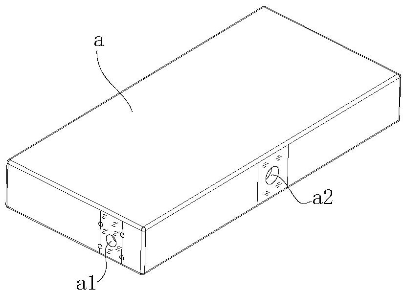
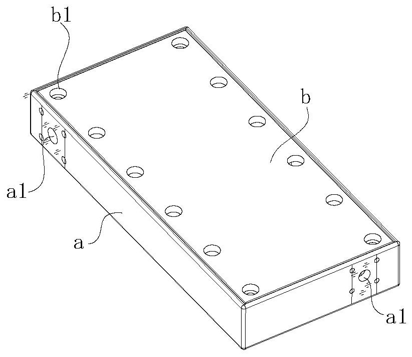
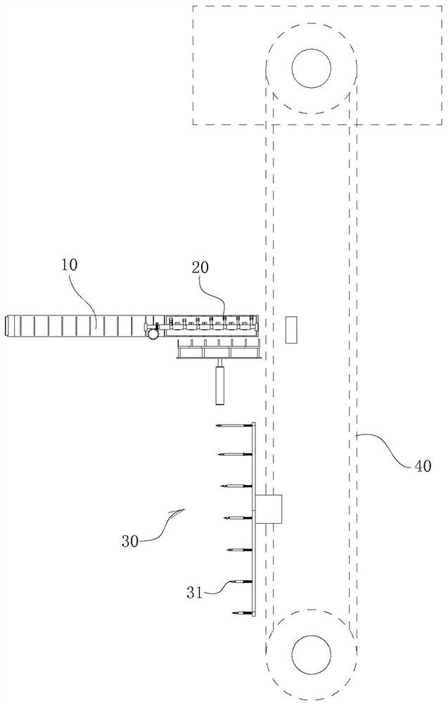
[0029] A coupler box hanging painting system, including a frame 10 for storing the coupler box, ...


PUM


Abstract

The invention relates to an object placing platform. The object placing platform comprises a plurality of object placing plates, wherein the surfaces of the object placing plates are horizontally andvertically arranged on a support plate in a sliding manner; the upper surfaces of the object placing plates form the surfaces for supporting the lower end surfaces of coupler box bodies; and lifting mechanisms are arranged below the object placing plates and drive the object placing plates to descend and form a stepped structure. According to the object placing platform, before a hanger passes through the object placing platform and after the object placing platform is full of the coupler box bodies, the object placing plates are arranged in a stepped manner in the front-rear direction under the action of the lifting mechanisms, and the object placing plate at the front-most end is low, so that the coupler box bodies on the object placing plates are arranged in the stepped manner, hangingholes of the coupler box bodies are exposed, and the hanging operation of couplers is convenient to realize; and the fixing relationship among plug connectors and a fixing support is matched with thefixing relationship of the object placing platform, so that it is ensured that the plug connectors are effectively inserted into the hanging holes.

Description

technical field [0001] The invention relates to the technical field of automation equipment, in particular to a storage table. Background technique [0002] combine figure 1 and figure 2 As shown, the coupler box of this type is designed to be in the shape of a cuboid as a whole. The box body includes the installation box a and the cover b. The electrical components of the coupler are installed in the installation box a, and at the two ends of the installation box a Wiring holes a1 are respectively provided on the side and the side of the installation box a, and junction points a2 are arranged on the side where the wiring holes a1 are provided on the installation box a. The coupler box body is made of aluminum alloy. After the box body is made, it needs to be painted. In the actual painting operation, the outer surface of the installation box a where the wiring hole a1 and the wiring point a2 are located is not painted. operation to avoid the influence of later paint on ...

Claims


Application Information

Patent Timeline
Patent Type & Authority Patents(China)
IPC IPC(8): B25H3/00
CPCB25H3/00
Inventor 曹茂兵郑梦云
Owner 安庆中巨机电科技有限公司
Why Eureka
Try Eureka