
Tool disassembling device for shear folding volume numerical control machine tool

A technology of dismantling device and numerical control machine tool, which is applied in the directions of hand-held tools, manufacturing tools, etc., can solve the problems of labor-saving dismantling device, increase the cost of replacement and maintenance, increase time cost, etc., so as to increase the difficulty of disassembly, reduce labor, The effect of improving usability

Inactive Publication Date: 2020-06-05
江苏龙胜机床制造有限公司
View PDF0 Cites 0 Cited by
  • Summary
  • Abstract
  • Description
  • Claims
  • Application Information

AI Technical Summary

Problems solved by technology

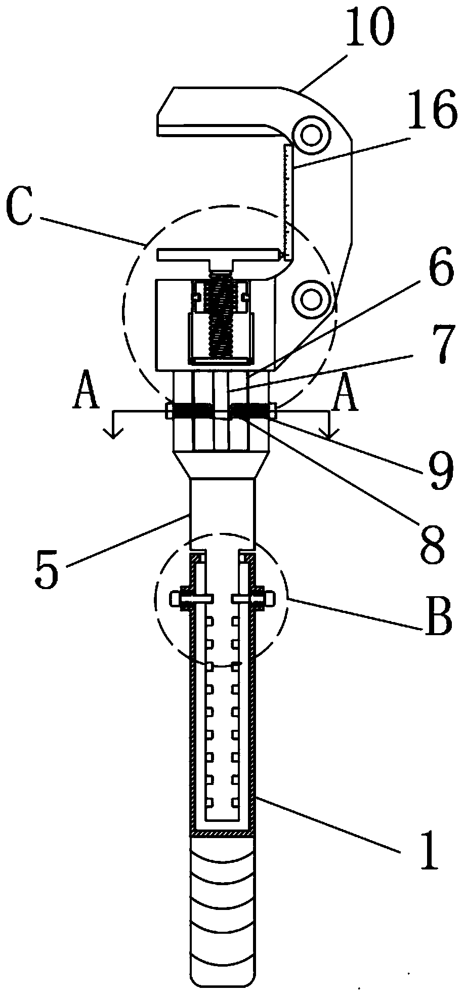
[0004] The object of the present invention is to provide a tool removal device for cutting and folding CNC machine tools to solve the problem that when the user removes the tool in the above background technology, the distance between the tools is relatively long and the length of the removal device is not enough due to the constraints of the internal environment of the CNC machine tool. , the disassembly is not cheap, and the general disassembly device is less labor-saving and easy to slip, which increases the difficulty of disassembly. When the user needs to disassemble the parts of the tool, the parts have the same style and different sizes, and the disassembly of the corresponding size needs to be replaced. device, which not only increases the time cost, but also increases the cost of replacement and maintenance. When the user disassembles the tool, due to the difference in the components of the tool, such as using a combination of bolts and screws, the user needs to replace different disassembly devices. question

Method used


Image

  • Tool disassembling device for shear folding volume numerical control machine tool
  • Tool disassembling device for shear folding volume numerical control machine tool
  • Tool disassembling device for shear folding volume numerical control machine tool

Examples


Embodiment Construction

[0021] The following will clearly and completely describe the technical solutions in the embodiments of the present invention with reference to the accompanying drawings in the embodiments of the present invention. Obviously, the described embodiments are only some, not all, embodiments of the present invention. Based on the embodiments of the present invention, all other embodiments obtained by persons of ordinary skill in the art without making creative efforts belong to the protection scope of the present invention.

[0022] see Figure 1-5 , an embodiment provided by the present invention:

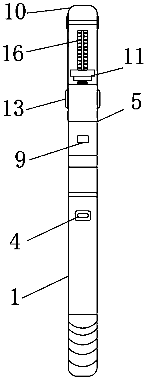
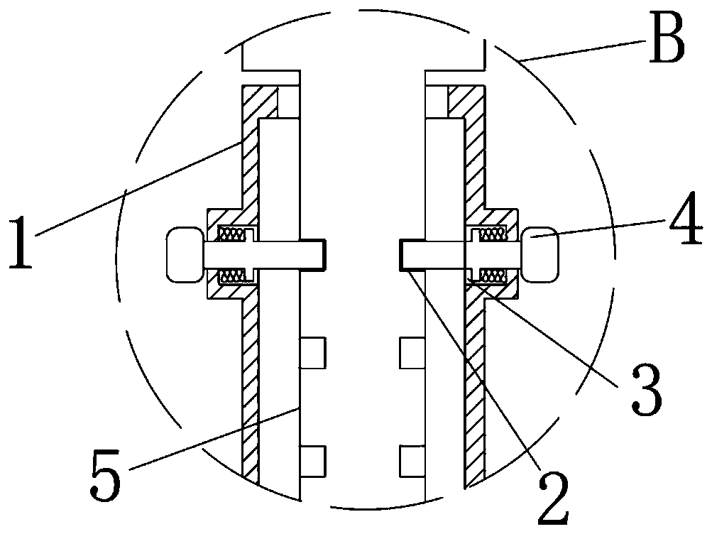
[0023] A tool removal device for cutting and folding CNC machine tools, including a handle 1 and a card slot 2, the bottom end of the adjustment rod 5 is glued with an anti-slip sleeve, and the surface of the anti-slip sleeve is evenly provided with annular anti-slip lines. When the user uses the device, The ring-shaped anti-slip pattern at the bottom of the adjustment rod 5 can incre...


PUM


Abstract

The invention discloses a tool disassembling device for a shear folding volume numerical control machine tool. The tool disassembling device comprises a handle and clamping grooves, wherein an adjusting rod is inserted into the top end of the handle, the clamping grooves are uniformly formed in the left side and the right side of the adjusting rod, a connecting groove is formed in the top end of the adjusting rod, fixing grooves are formed in the left end and the right end of a connecting block, a disassembling plate is arranged in a disassembling head, a second control groove is formed in thebottom end of the front surface of the disassembling head in a penetrating mode, and the top end of a screw rod is welded and fixed to the disassembling plate. According to the tool disassembling device, when the tool disassembling device is used by a user, the phenomenon that because the distance of a tool is long, the length of the disassembling device is insufficient and the labor is not savedcaused by slipping of the disassembling device, the disassembling difficulty is increased is avoided; and when the user needs to disassemble parts with the same type and different sizes, the disassembling device of the corresponding size is not required to be replaced, and when the user needs to replace different disassembling devices, the whole disassembling device does not need to be replaced.

Description

technical field [0001] The invention relates to the technical field of cutter removal devices, in particular to a cutter removal device for a numerically controlled machine tool for shearing and folding. Background technique [0002] With the continuous development of science and technology, it has also driven the development of the machinery manufacturing industry. As an indispensable part of the machinery manufacturing industry, CNC machine tools have higher and higher requirements for tool disassembly devices. [0003] At this stage, the precision requirements of CNC machine tools are constantly improving, and the time and device costs for subsequent maintenance and tool replacement are also getting higher and higher. When the user disassembles the tool, it is restricted by the internal environment of the CNC machine tool, and the distance between the tool disassembly is relatively long. , and the disassembly part may be close to the tool or other parts, the space is insu...

Claims


Application Information

Patent Timeline
Patent Type & Authority Applications(China)
IPC IPC(8): B25B27/00B25G1/04B25G3/30
CPCB25B27/00B25G1/04B25G3/30
Inventor 吴文亮
Owner 江苏龙胜机床制造有限公司
Learn More