
a vibration motor

A technology of vibrating motors and mounting plates, which is applied in electric components, manufacturing motor generators, reciprocating/oscillating/vibrating magnetic circuit components, etc., which can solve the problem of changes in the inner diameter of bearings, unsmooth rotation of rotors, and influences on bearing inner diameters and steel shafts Coordination and other issues to achieve the effect of reducing the space of the flow channel, increasing the area of ​​the magnetic field, and reducing the difficulty of operation

Active Publication Date: 2021-05-18
阜南县特立电子有限公司
View PDF8 Cites 0 Cited by
  • Summary
  • Abstract
  • Description
  • Claims
  • Application Information

AI Technical Summary

Problems solved by technology

[0003] The purpose of the present invention is to provide a vibration motor to solve the problem that when the existing vibration motor is applied to different electronic products, due to the volume limitation of the electronic product itself, the operation of the vibration motor is difficult, the cost is high, and the existing Due to the large contact area of ​​the internal brush of the vibration motor, it is easy to generate debris due to wear and accumulate in the gap between the brush claws during operation, resulting in noise, current overload, and heat generation when the motor starts and rotates. etc., affect the service life of the vibration motor; when the existing vibration motor performs the rotor forming process, the assembly of the rotor is usually made by fixing the PCB board, coil, bearing and eccentric hammer through injection molding of polybutylene terephthalate , so that the inner diameter of the bearing is easily changed due to the force in the injection molding process, which in turn affects the cooperation between the inner diameter of the bearing and the steel shaft, making the rotor not rotate smoothly, and thus affecting the normal operation of the vibration motor.

Method used


Image

  • a vibration motor
  • a vibration motor
  • a vibration motor

Examples


Embodiment Construction

[0029] The technical solutions of the present invention will be clearly and completely described below in conjunction with the embodiments. Apparently, the described embodiments are only some of the embodiments of the present invention, not all of them. Based on the embodiments of the present invention, all other embodiments obtained by persons of ordinary skill in the art without creative efforts fall within the protection scope of the present invention.

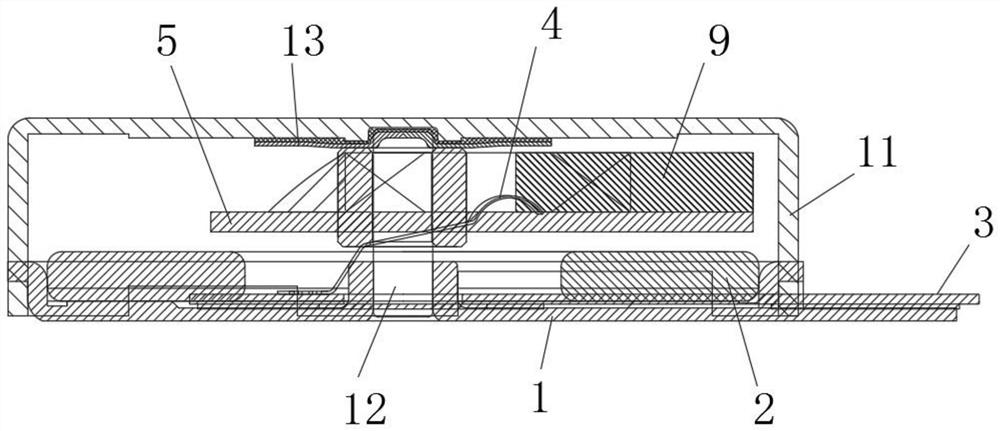
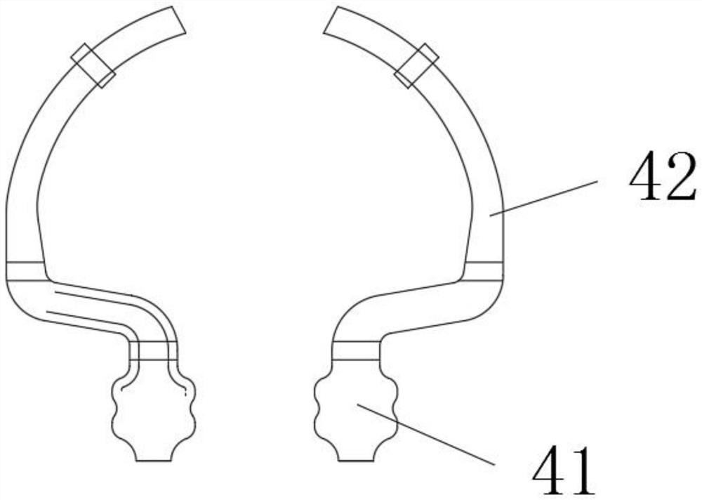
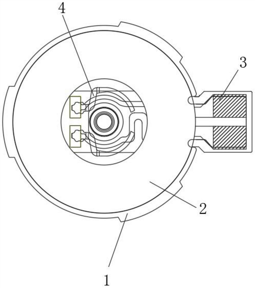
[0030] see Figure 1-8 , a vibration motor, including: magnetic steel 2, first mounting plate 3, electric brush 4, second mounting plate 5, bearing 7, eccentric hammer 8, coil 9, glue layer 10, upper shell 11, steel shaft 12 , slide 13, the first mounting plate 3 is an F-PCB board, that is, a flexible circuit board, the bottom of the first mounting plate 3 is glued to the lower housing 1, and the upper end of the first mounting plate 3 is welded and fixed with a brush 4. The upper end of the brush 4 is provided with a magn...


PUM


Abstract

The invention discloses a vibration motor. An eccentric hammer is arranged at one end of a second mounting plate, and coils are symmetrically arranged at both ends of the eccentric hammer. The bearing, the eccentric hammer and the coil are all glued and fixed to the second mounting plate by UV glue. The top of the shaft is tightly fitted with the bearing, so that it is no longer necessary to inject the bearing, eccentric hammer and coil through polybutylene terephthalate when forming the rotor, which is different from the traditional polybutylene terephthalate injection molding Compared with polybutylene terephthalate, the minimum space of the flow channel needs to be more than 0.2mm during injection molding, so that the rotor needs to shrink the size of parts such as the coil wire diameter in the original small space to meet the forming conditions when designing the rotor. The adhesive fixation of UV glue makes the flow channel space of glue only need 0.05mm to meet the fixing needs, so that there is more space for the parts inside the rotor, which greatly reduces the difficulty of operation and reduces the production cost.

Description

technical field [0001] The invention relates to the field of motors, in particular to a vibration motor, which belongs to the technical field of vibration motor applications. Background technique [0002] In recent years, social intelligence technology has developed by leaps and bounds. People have higher and higher requirements for the perfection of functions of intelligent and convenient communication tools. The word "smart" appears more and more frequently in life, for example: smart phones, Smart phone watches, smart sports bracelets, smart bluetooth earphones... all the functions of smart electronic products are becoming more and more perfect, and they are more and more in line with the needs of customers. Mobile phones now play an important role in people's life and work. The vibration reminder function allows customers to see information at the first time, so as not to miss important information. With the development of technology, more electronics-related products s...

Claims


Application Information

Patent Timeline
Patent Type & Authority Patents(China)
IPC IPC(8): H02K1/34H02K7/06H02K33/00H02K15/00
CPCH02K1/34H02K7/061H02K15/00H02K33/00
Inventor 李伟德
Owner 阜南县特立电子有限公司
Learn More