Armature molded structure

A technology of mold and armature, applied in the direction of magnetic circuit shape/style/structure, winding conductor shape/style/structure, winding insulation shape/style/structure, etc. The effect of reducing moment and securing strength

Pending Publication Date: 2020-06-02
SANYO DENKI CO LTD
View PDF1 Cites 0 Cited by
  • Summary
  • Abstract
  • Description
  • Claims
  • Application Information

AI Technical Summary

Problems solved by technology

As a result, there will be a problem that the torque will decrease

Method used


Image

  • Armature molded structure
  • Armature molded structure
  • Armature molded structure

Examples


Embodiment Construction

[0019] In the following detailed description, for purposes of explanation, numerous specific details are set forth in order to provide a thorough understanding of the disclosed embodiments. It may be evident, however, that one or more embodiments may be practiced without these specific details. In other instances, well-known structures and devices are shown schematically in order to simplify the drawings.

[0020] Hereinafter, a mold structure of a motor armature according to an embodiment of the present invention will be described in detail with reference to the drawings.

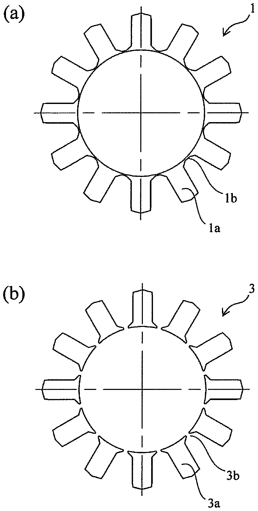
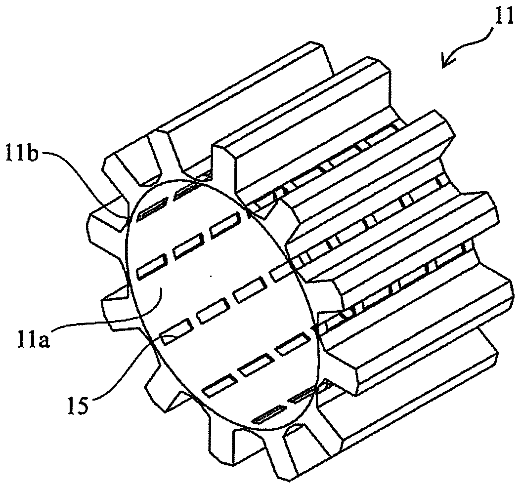
[0021] figure 1 It is an example of the core sheet which shows the iron core used for the mold structure of the motor armature (stator) which concerns on one Embodiment of this invention. figure 1 (a) is a plan view showing a configuration example of the first core sheet. figure 1 (b) is a plan view showing one configuration example of the second core sheet. figure 2 It is a perspective view showing a...


PUM


Abstract

An armature molded structure includes a cylindrical iron core used for a molded structure of a motor armature; a winding; and molding resin, wherein the iron core includes first core sheets and secondcore sheets, the first core sheet includes first magnetic poles placed along a circumferential direction of the iron core, tip portions, on an inner peripheral side of the iron core, of adjacent first magnetic poles form a coupling portion coupling the adjacent first magnetic poles, the second core sheet includes second magnetic poles placed along the circumferential direction of the iron core, tip portions, on the inner peripheral side of the iron core, of adjacent second magnetic poles form a non-coupling portion separating the adjacent second magnetic poles, the first and second core sheets are laminated along a central axis direction of the iron core in such a manner that the coupling portions coincide with each other, the non-coupling portions coincide with each other, the coupling portion and the non-coupling portion coincide with each other, the winding is wound around the first and second magnetic poles of the laminated first and second core sheets, the first and second core sheets and the winding are molded with the molding resin, the non-coupling portion delimits an opening window portion in an inner peripheral surface of the iron core, and the opening window portion isfilled with the molding resin.

Description

[0001] Cross References to Related Applications [0002] This application claims priority from Japanese Patent Application No. 2018-220152 filed with the Japan Patent Office on November 26, 2018, the entire contents of which are incorporated herein by reference. technical field [0003] The present invention relates to an armature mold structure for a motor. Background technique [0004] There is known a technique of forming an armature mold structure by resin molding. For example, according to Japanese Patent Laid-Open Publication No. 2016-135022, the resin flows into the magnetic pole tip end located on the inner surface side of the iron core constituting the armature. [0005] The distance of the gap between the armature and the rotor of the motor is preferably such that a constant distance to the inner circumference of the armature core is ensured. However, the resin flows into the magnetic pole tip. Therefore, it is necessary to ensure a constant distance to the insc...

Claims


Application Information

Patent Timeline
Patent Type & Authority Applications(China)
IPC IPC(8): H02K1/18H02K1/14H02K3/18H02K3/38
CPCH02K1/185H02K1/148H02K3/18H02K3/38H02K15/024H02K1/12H02K3/522H02K5/08H02K15/02H02K1/146H02K1/18
Inventor 堀内学相良弘树北岛纯清水麻衣松下孝
Owner SANYO DENKI CO LTD
Why Eureka
Try Eureka