rotating electrical machine

A technology of rotating electrical machines and rotors, applied in the field of rotating electrical machines, can solve problems such as coil flying out, achieve the effects of preventing accidental flying out, ensuring occupancy, and suppressing the reduction of torque

Active Publication Date: 2019-01-15
SUZUKI MOTOR CORP
View PDF6 Cites 0 Cited by
  • Summary
  • Abstract
  • Description
  • Claims
  • Application Information

AI Technical Summary

Problems solved by technology

In such a rotating electrical machine in which coils are wound around the salient poles of the rotor, a large centrifugal force acts on the coils when the rotor rotates, so the coils may accidentally fly out of the rotor slots.

Method used


Image

  • rotating electrical machine
  • rotating electrical machine
  • rotating electrical machine

Examples


Embodiment Construction

[0041] Hereinafter, embodiments of the present invention will be described with reference to the drawings. Figure 1 to Figure 12 It is a figure explaining the rotating electrical machine which concerns on one Embodiment of this invention.

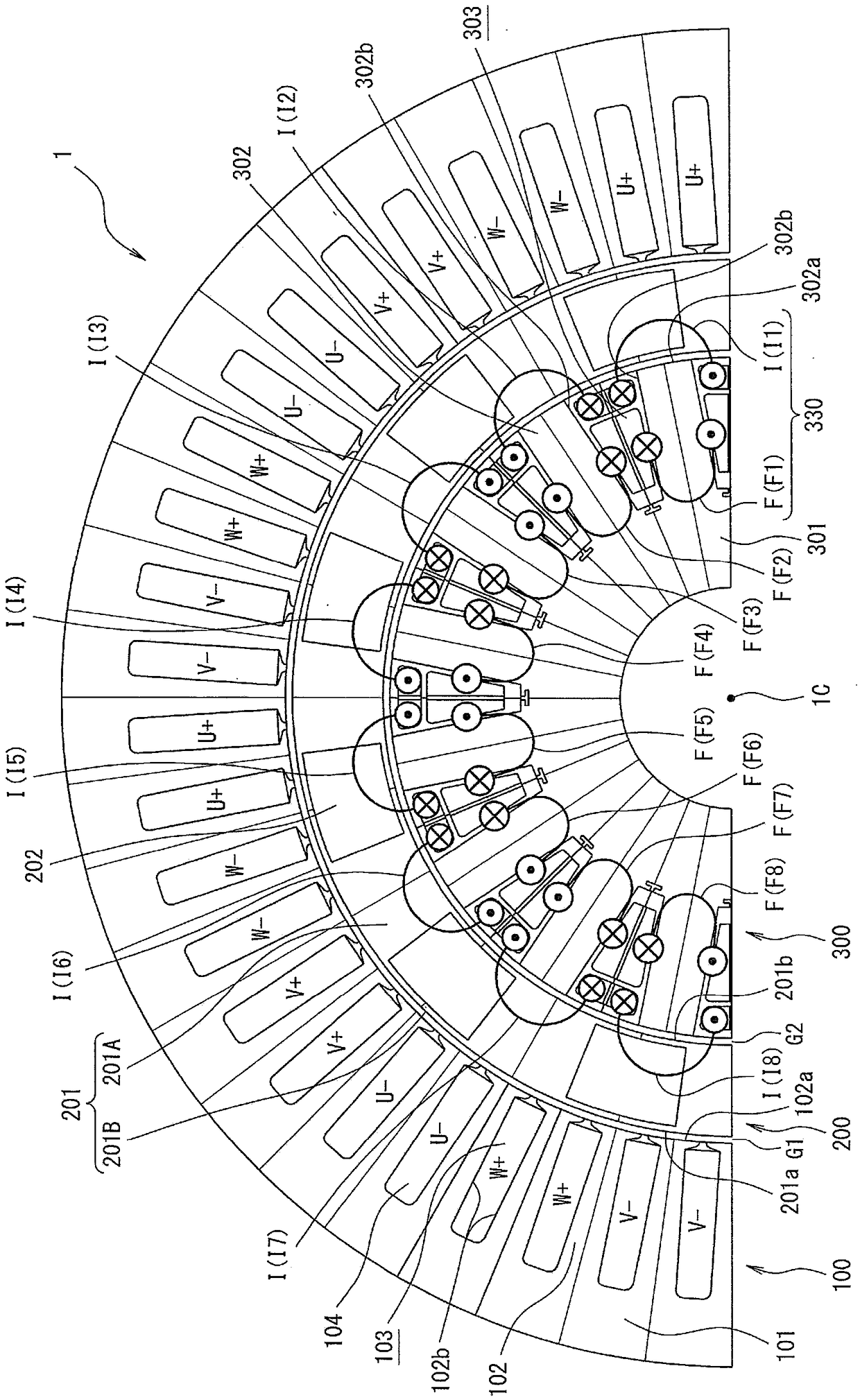
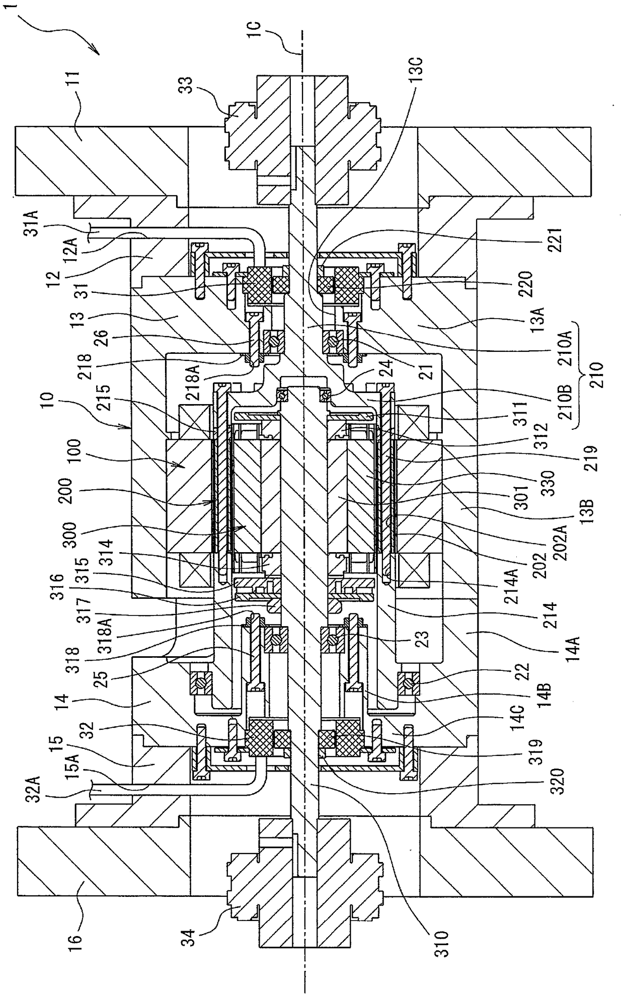
[0042] exist figure 1 Among them, the rotating electrical machine 1 is constituted as a rotating electrical machine of a double-rotor type, and includes: a stator 100 formed in a cylindrical shape; an outer rotor 200 as a second rotor provided on the rotating shaft 1C side of the stator 100; An inner rotor 300 serving as a first rotor on the rotating shaft 1C side of the rotor 200 . The outer rotor 200 and the inner rotor 300 are respectively supported so as to be relatively rotatable around the rotation axis 1C. also, figure 1 A radial cross-sectional view of 180 degrees (1 / 2) out of 360 degrees of mechanical angle is shown. The inner rotor 300 constitutes a rotor in the present invention.

[0043] The stator 100 includes a stator ...


PUM


Abstract

The invention provides a rotary motor which can ensure an occupation rate of coils of a rotor, restrain decrease of torque and apply a maintenance component to prevent the coils from fly out accidentally from a groove of the rotor. A rotor winding (330) wound on an inner rotor (300) is immobilized by liquid solidification materials such as paints and resin; and the maintenance component (350) is formed by insulation paper which can absorb the liquid solidification materials. In the inner rotor (300), insulation bodies (340) would by the rotor winding (330) are installed on each rotor tooth (302); the maintenance component (350) is disposed between the insulation body (340) installed on the rotor teeth (302); and the rotor winding (330) is fixed through injection of the liquid solidification materials between the insulation bodies (340) installed on the rotor teeth (302).

Description

technical field [0001] The present invention relates to a rotating electric machine including a rotor in which a plurality of salient pole portions wound with coils interlinked with magnetic flux generated on a stator side are arranged in parallel in the circumferential direction. Background technique [0002] As a rotating electric machine mounted on a hybrid vehicle or the like, a rotating electric machine including: a stator having an armature coil that generates magnetic flux by energization; Rotors juxtaposed upwards. In such a rotating electrical machine in which coils are wound around the salient poles of the rotor, a large centrifugal force acts on the coils when the rotor rotates, and thus the coils may unintentionally fly out of the rotor slots. [0003] On the other hand, the rotating electric machine described in patent document 1 is known among the conventional rotating electric machines. The rotating electric machine described in Patent Document 1 is provided...

Claims


Application Information

Patent Timeline
Patent Type & Authority Patents(China)
IPC IPC(8): H02K19/28
CPCH02K19/28H02K3/527H02K7/183H02K16/02H02K19/103H02K19/12H02K2203/12Y02E10/72
Inventor 久保田芳永青山真大
Owner SUZUKI MOTOR CORP
Why Eureka
Try Eureka