Rotors, permanent magnet embedded motors, compressors, and air conditioners

A technology of permanent magnets and rotors, which is applied to synchronous motors, compressors, and electric components with stationary armatures and rotating magnets. It can solve the problems of increased torque ripple and reduce torque ripple and reduce torque. Sustained effect

Active Publication Date: 2020-02-28
MITSUBISHI ELECTRIC CORP
View PDF4 Cites 0 Cited by
  • Summary
  • Abstract
  • Description
  • Claims
  • Application Information

AI Technical Summary

Problems solved by technology

[0003] However, compared with an embedded permanent magnet motor that does not use reluctance torque, an embedded permanent magnet motor that utilizes high reluctance torque tends to cause ripples in the torque waveform, resulting in increased torque ripple. topic

Method used


Image

  • Rotors, permanent magnet embedded motors, compressors, and air conditioners
  • Rotors, permanent magnet embedded motors, compressors, and air conditioners
  • Rotors, permanent magnet embedded motors, compressors, and air conditioners

Examples


Embodiment approach 1

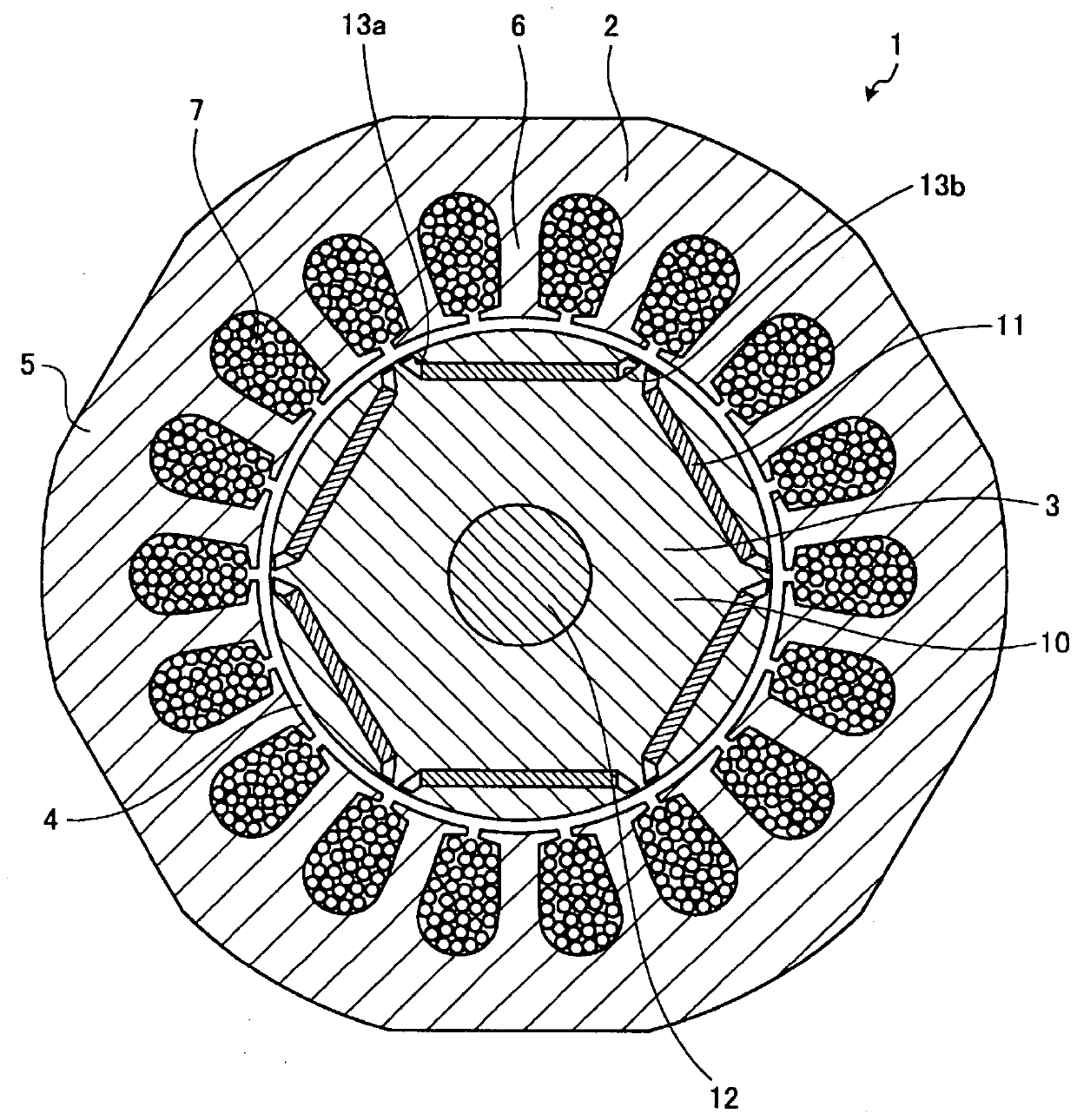
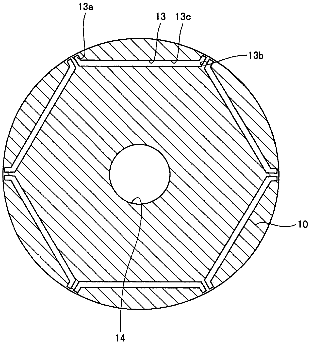
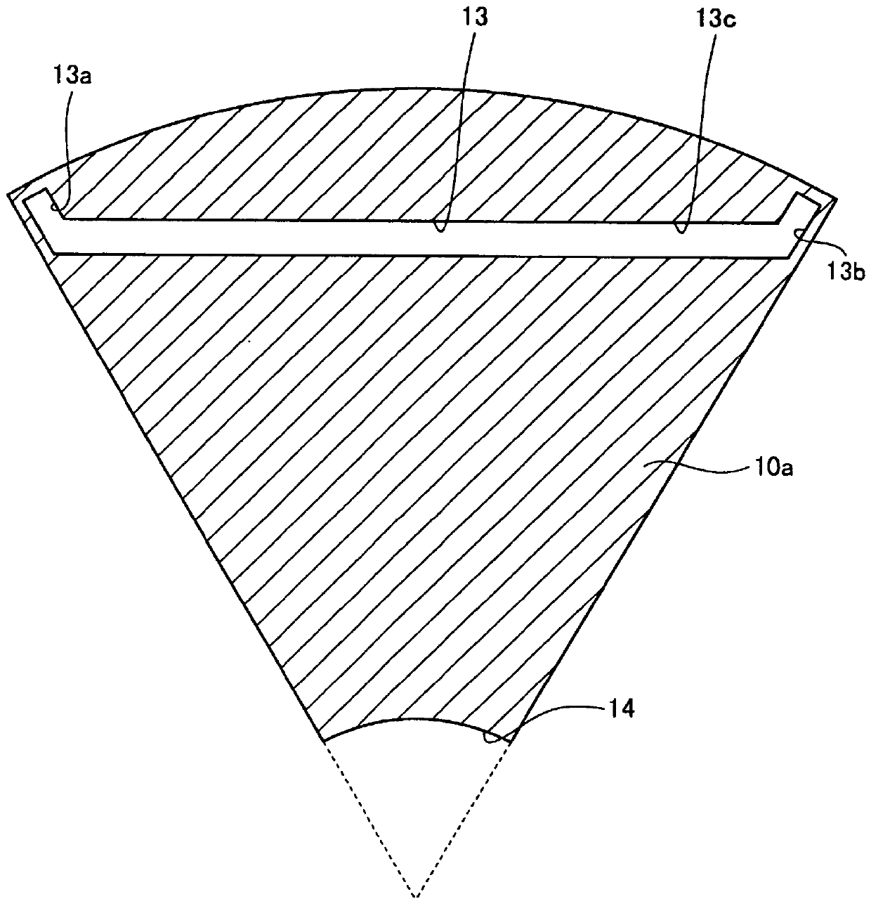
[0026] figure 1 is a cross-sectional view showing the structure of the permanent magnet embedded motor according to the present embodiment, figure 2 It is a sectional view of the rotor core of this embodiment. As described later, figure 1 as well as figure 2 It is a figure which shows the cross-sectional structure of the 1st core block among the 1st and 2nd core blocks which comprise a rotor core.

[0027] An embedded permanent magnet motor 1 includes an annular stator 2 and a rotor 3 disposed radially inside of the stator 2 with a gap 4 interposed therebetween.

[0028] The stator 2 includes an annular stator core 5 and a coil 7 wound around a plurality of teeth 6 formed on the inner peripheral surface of the stator core 5 . The teeth 6 are arranged at equal intervals in the circumferential direction of the stator 2 and extend in the radial direction of the stator core 5 .

[0029] The winding 7 is distributedly wound. In distributed winding, the winding 7 is wound ac...

Embodiment approach 2

[0062] Figure 11 It is a figure which shows the structure of the air conditioner which concerns on this embodiment. The air conditioner 100 according to this embodiment includes an indoor unit 101 and an outdoor unit 102 connected to the indoor unit 101 . The outdoor unit 102 includes the compressor 103 according to this embodiment. The embedded permanent magnet motor 1 of the first embodiment is used for the compressor 103 . In addition, the permanent magnet embedded motor 1 includes Modifications 1 and 2 described in the first embodiment.

[0063] Energy-saving performance is required for the air conditioner 100, and high efficiency is required. Furthermore, in order to suppress the vibration and noise which generate|occur|produce from the air conditioner 100 below a reference value, it is necessary to reduce the vibration and noise which generate|occur|produce from the compressor 103. The embedded permanent magnet motor 1 according to Embodiment 1 can suppress torque r...


PUM


Abstract

The rotor (3) of the permanent magnet embedded type motor includes: an annular rotor core (10) having a plurality of magnet insertion holes (13) formed in the circumferential direction; and a permanent magnet (11) inserted into each magnet insertion hole (13), the rotor core (10) is a core block (10a) that does not have a slit (15a, 15b) between each magnet insertion hole (13) and the outer peripheral surface of the rotor core (10) and each magnet is inserted Core blocks (10b) with slits (15a, 15b) between the holes (13) and the outer peripheral surface of the rotor core (10) are alternately stacked in the axial direction of the rotor core (10), and the slits (15a) The ends (11a) of the permanent magnets (11) are arranged radially, and the slits (15b) are arranged radially with the ends (11b) of the permanent magnets (11).

Description

technical field [0001] The present invention relates to a rotor having permanent magnets embedded in a rotor core, an embedded permanent magnet motor including the rotor, a compressor including the embedded permanent magnet motor, and an air conditioner including the compressor. Background technique [0002] In recent years, due to increased awareness of energy conservation, high-efficiency motors have been demanded, and many embedded permanent magnet motors have been proposed that achieve high efficiency by using rare-earth magnets with high residual magnetic flux density and high coercive force for the rotor. Furthermore, by employing a structure in which the permanent magnets are embedded in the rotor, not only the magnet torque but also the reluctance torque can be utilized, so that a high-efficiency motor can be constructed. The reluctance torque is proportional to the difference between the inductances of the d-axis and the q-axis. Therefore, in order to increase the r...

Claims


Application Information

Patent Timeline
Patent Type & Authority Patents(China)
IPC IPC(8): H02K1/27
CPCH02K1/276H02K21/14H02K2213/03F25B31/02H02K1/02H02K1/148H02K29/03H02K2201/06
Inventor 石川淳史仁吾昌弘
Owner MITSUBISHI ELECTRIC CORP
Why Eureka
Try Eureka