
Inertia parameter determination method and device for inertia compensation equipment in power system

A power system and inertial parameter technology, applied in the direction of reducing/preventing power oscillation, etc., can solve problems such as insufficient inertia support of the power system

Active Publication Date: 2020-06-02
CHINA ELECTRIC POWER RES INST
View PDF7 Cites 9 Cited by
  • Summary
  • Abstract
  • Description
  • Claims
  • Application Information

AI Technical Summary

Problems solved by technology

[0005] Aiming at the deficiencies of the prior art, the present invention provides a method and device for determining the inertial parameters of the inertia compensation equipment in the power system, aiming to solve the problem of insufficient inertia support in the power system

Method used


Image

  • Inertia parameter determination method and device for inertia compensation equipment in power system
  • Inertia parameter determination method and device for inertia compensation equipment in power system
  • Inertia parameter determination method and device for inertia compensation equipment in power system

Examples


Embodiment Construction

[0029] Exemplary embodiments of the present invention will now be described with reference to the drawings; however, the present invention may be embodied in many different forms and are not limited to the embodiments described herein, which are provided for the purpose of exhaustively and completely disclosing the present invention. invention and fully convey the scope of the invention to those skilled in the art. The terms used in the exemplary embodiments shown in the drawings are not limiting of the present invention. In the figures, the same units / elements are given the same reference numerals.

[0030] Unless otherwise stated, the terms (including scientific and technical terms) used herein have the meanings commonly understood by those skilled in the art. In addition, it can be understood that the terms defined by commonly used dictionaries should be understood as having consistent meanings in the context of their related fields, and should not be understood as idealiz...


PUM


Abstract

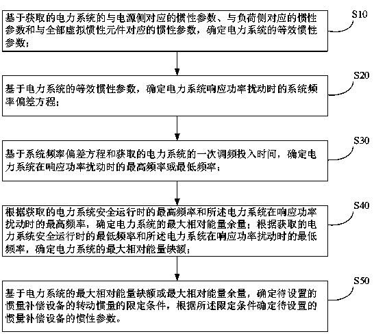
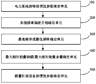
The invention discloses a method and device for determining inertia parameters of inertia compensation equipment in a power system. The method comprises the steps of determining equivalent inertia parameters of the power system; determining a system frequency deviation equation when the power system responds to power disturbance; based on the system frequency deviation equation and the obtained primary frequency modulation input time of the power system, determining the highest frequency or the lowest frequency of the power system in response to power disturbance; determining the maximum relative energy margin of the power system; determining the maximum relative energy vacancy of the power system; determining a limiting condition of the rotational inertia of the inertia compensation equipment to be set; and determining inertia parameters of the inertia compensation equipment to be set according to the limiting condition, wherein the inertia compensation equipment is connected to a grid-connected point of a new energy field station in parallel, and the inertia compensation equipment suppresses the frequency change of the power system by releasing or storing rotation kinetic energy.The method is low in requirement for computing resources, high in solving efficiency and good in accuracy.

Description

technical field [0001] The invention relates to the technical field of power system operation and control, in particular to a method and device for determining inertia parameters of inertia compensation equipment in the power system. Background technique [0002] On August 9, 2019, there was a major power outage in the UK. The process is roughly as follows: For some reason, the Little Barford gas-fired power station in the North Sea grid was shut down. After the gas-fired power station is disconnected from the grid, the power generation load lost by the grid reduces the frequency of the power system. On the other hand, due to the insufficient ability of the wind turbines in the North Sea Power Grid to withstand low frequencies, the reduction in the frequency of the power system caused a large number of wind turbines to go off-grid, so the output of the wind farm dropped sharply, which further increased the power generation load lost by the power grid, resulting in a continu...

Claims


Application Information

Patent Timeline
Patent Type & Authority Applications(China)
IPC IPC(8): H02J3/24
CPCH02J3/24
Inventor 张健李文锋贺静波金一丁魏巍贾媛李莹陶向宇王官宏霍乾涛
Owner CHINA ELECTRIC POWER RES INST
Learn More