Eureka AIR delivers breakthrough ideas for toughest innovation challenges, trusted by R&D personnel around the world.

Dynamic RS coverage in multi-hop cellular networks

a multi-hop, cellular network technology, applied in power management, sustainable buildings, high-level techniques, etc., can solve the problems of not being able to effectively control load conditions, current systems, and failure to effectively increase the coverage of relay systems, so as to increase cell coverage, decrease cell coverage, and increase cell coverage

Inactive Publication Date: 2007-08-09
SAMSUNG ELECTRONICS CO LTD
View PDF9 Cites 32 Cited by
  • Summary
  • Abstract
  • Description
  • Claims
  • Application Information

AI Technical Summary

Benefits of technology

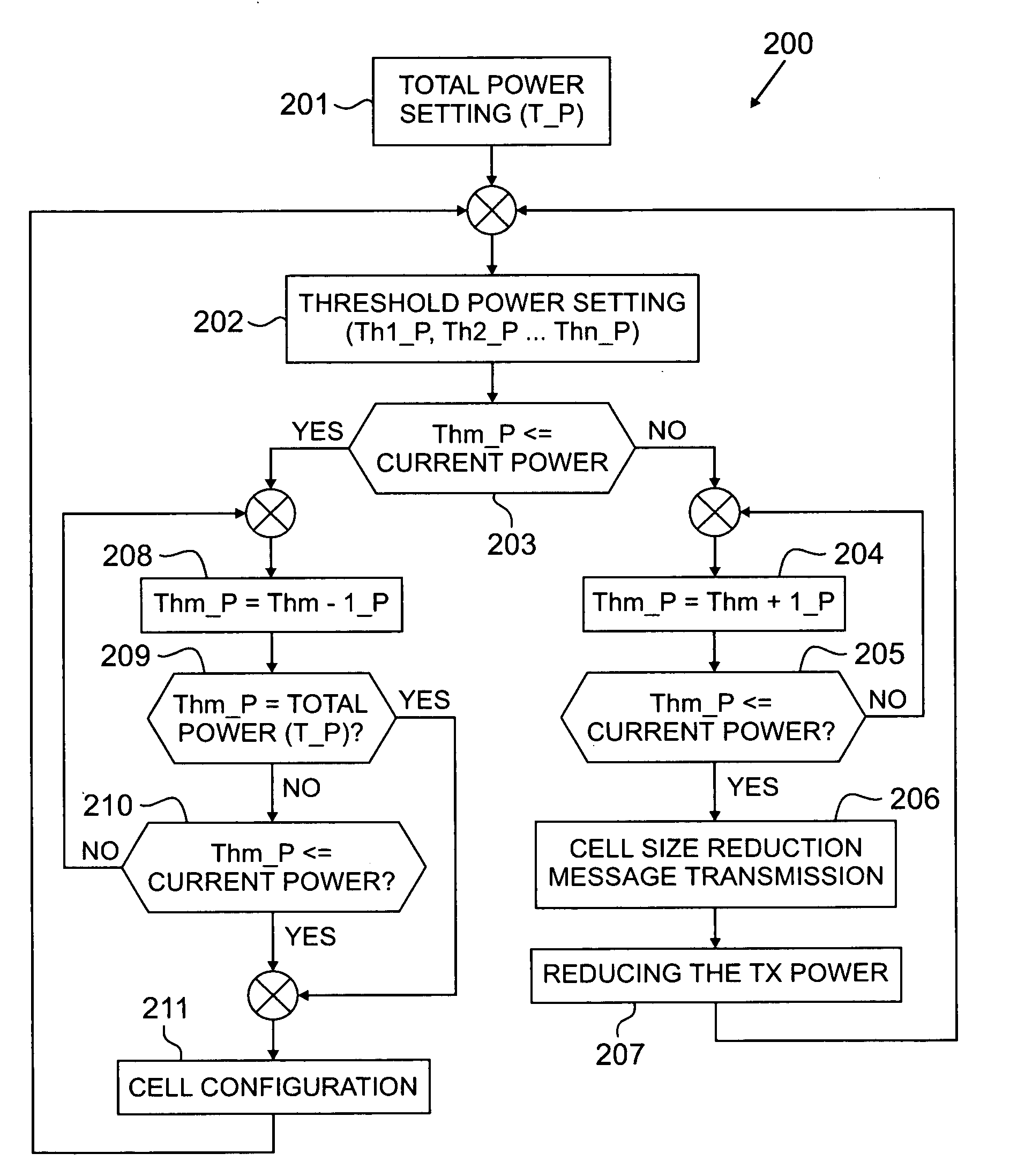
[0007]In another embodiment of the disclosure, a method is provided for managing cell coverage in a wireless network having a relay station in communication with a mobile station. The method includes comparing a threshold power setting of a relay station with a current load setting of the relay station. When the threshold power setting is greater than the current load setting, the method includes increasing the cell coverage.
[0008]In still another embodiment, a relay station is provided for use in a wireless network. The relay station includes a controller. The controller is capable of comparing a threshold power setting of a relay station with a current power setting of the relay station. When the threshold power setting is greater than the current power setting, the controller increments the threshold power setting; and decreases the cell coverage. If, however, the threshold power setting is less than or equal to the current power setting, the controller decrements the threshold power setting until the threshold power setting is equal to a total power setting of the relay station and increases cell coverage.

Problems solved by technology

Current systems, however, fail to effectively increase relay system coverage while employing power saving mechanisms for the relay station.
Moreover, there are no procedures currently available for effectively controlling load conditions, such as the number of user traffic channels supported and the user data rates.

Method used


Image

  • Dynamic RS coverage in multi-hop cellular networks
  • Dynamic RS coverage in multi-hop cellular networks
  • Dynamic RS coverage in multi-hop cellular networks

Examples


Embodiment Construction

[0014]FIGS. 1 through 3, discussed below, and the various embodiments used to describe the principles of the present disclosure in this patent document are by way of illustration only and should not be construed in any way to limit the scope of the disclosure. Those skilled in the art will understand that the principles of the present disclosure may be implemented in any suitably arranged wireless network.

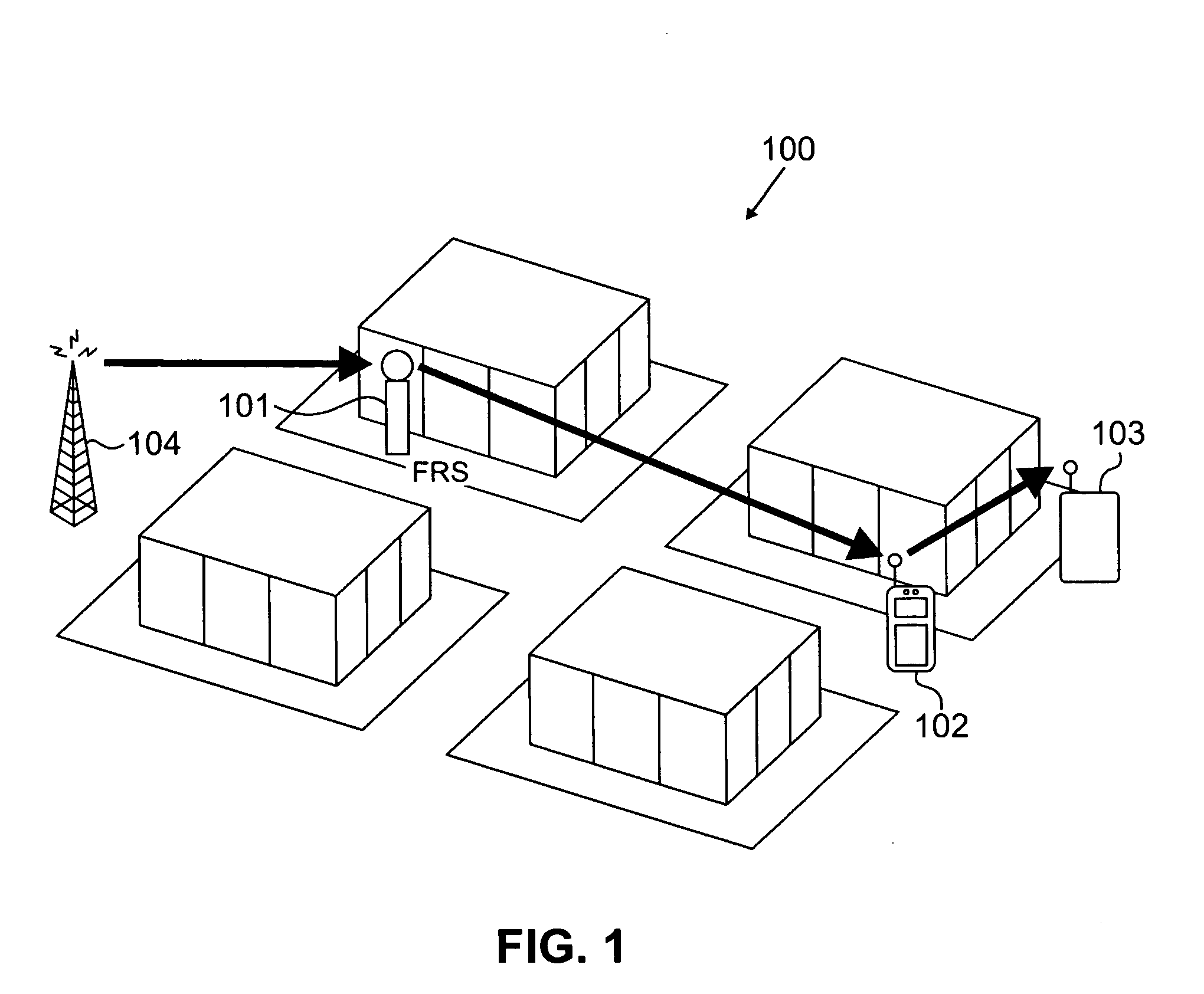
[0015]FIG. 1 illustrates an exemplary multi-hop cellular network 100 according to an embodiment of the present disclosure. Multi-hop cellular network 100 preferably includes the use of, for example, a fixed relay station (FRS) 101 and a mobile relay station (MRS) 102. Multi-hop cellular network 100 forms a multi-hop link between a base station (BS) 104 and a mobile station (MS) 103 served by BS 104. Multi-hop cellular network 100 extends the coverage range, user data rates and coverage area of a base station (BS) 104. Multi-hop cellular network 100 provides a method and procedure f...


PUM


Abstract

For use in a wireless network, a controller for relay stations. The relay station increases cell coverage and user data rates while employing power consumption saving techniques. The relay station compares a threshold power setting with a current power setting. If the threshold power setting is greater than the current power setting, the relay station increments the threshold power setting and decreases the cell coverage. If the threshold power setting is less than or equal to the current power setting, the relay station decreases the threshold power setting until the threshold power setting is equal to a total power setting of the relay station. The relay station also employs load balancing techniques by comparing a threshold power setting with a current load setting. If the threshold power setting is greater than the current load setting, the relay station increases the cell coverage based on the available bandwidth.

Description

CROSS-REFERENCE TO RELATED APPLICATION AND CLAIM OF PRIORITY[0001]The present application is related to U.S. Provisional Patent No. 60 / 771,617, filed Feb. 8, 2006, entitled “DYNAMIC RS COVERAGE IN THE MULTI-HOP CELLULAR NETWORKS”. U.S. Provisional Patent No. 60 / 771,617 is assigned to the assignee of the present application and is hereby incorporated by reference into the present disclosure as if fully set forth herein. The present application hereby claims priority under 35 U.S.C. §119(e) to U.S. Provisional Patent No. 60 / 771,617.TECHNICAL FIELD OF THE INVENTION[0002]The present application relates generally to wireless communication networks and, more specifically, to signal relay stations.BACKGROUND OF THE INVENTION[0003]Relay stations are added to wireless communications networks to increase the coverage range, user data rates, or both, at the periphery of the cellular coverage area. A multi-hop network facilitates communication between a base station and mobile stations in the e...

Claims


Application Information

Patent Timeline
Patent Type & Authority Applications(United States)
IPC IPC(8): H04B7/00H04B7/24H04W16/00H04B7/26
CPCH04B7/15535H04B7/2606Y02B60/50H04W52/343H04W16/26H04W84/18Y02D30/70
Inventor KOO, CHANGHOIRAJKOTIA, PURVA R.CLEVELAND, JOSEPH R.
Owner SAMSUNG ELECTRONICS CO LTD
Why Eureka
Eureka Blog
Learn More