Noise reduction installation structure of transformer shell

An installation structure and technology for transformers, applied in the field of transformers, can solve problems such as lack of noise reduction function, achieve simple and fast connection operation, improve shock absorption effect, and avoid loosening effects

Inactive Publication Date: 2020-06-02
保定意源达电力设备制造有限公司
View PDF3 Cites 0 Cited by
  • Summary
  • Abstract
  • Description
  • Claims
  • Application Information

AI Technical Summary

Problems solved by technology

[0003] The transformer will generate relatively strong noise during operation, and most of the existing transformer installation structures do not have the noise reduction function, which will have a certain negative impact on the working environment. Therefore, it is necessary to improve the transformer to improve the working environment

Method used


Image

  • Noise reduction installation structure of transformer shell
  • Noise reduction installation structure of transformer shell
  • Noise reduction installation structure of transformer shell

Examples


Embodiment 1

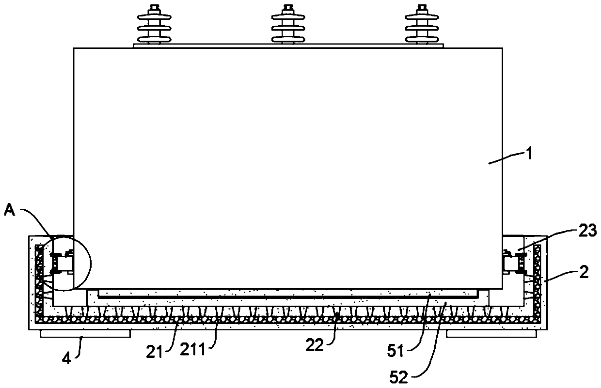
[0023] see Figure 1~3 , in an embodiment of the present invention, a noise reduction installation structure for a transformer housing includes a transformer housing 1 and a mounting base 2; the transformer housing 1 is connected to the mounting base 2 through a connection structure, and a cavity 21 is opened in the mounting base 2, The cavity 21 is filled with sound-absorbing cotton 211, and the shell wall of the mounting seat 2 is provided with a perforation 22 communicating with the cavity 21. The perforation 22 is trumpet-shaped and its big mouth is set towards the direction of the transformer shell 1, so that during operation The generated noise will enter into the cavity 21 through the perforation 22, and the noise will be weakened by the perforation 22 for the first time, and then the noise will be weakened by the sound-absorbing cotton 211 in the cavity 21 for the second time, thus effectively reducing the noise. noise effect.

[0024] Since part of the noise generate...

Embodiment 2

[0029] see figure 1 and 4 , the embodiment of the present invention describes the connection structure in detail on the basis of embodiment 1, specifically:

[0030] The connecting structure includes a rotating sleeve 31, a block 32 and a slot 34. The rotating sleeve 31 is rotatably connected to the outer wall of the mounting base 2, and the locking block 32 is inserted in the rotating sleeve 31 and connected to the rotating sleeve 31 through thread fit. , the side of the clamping block 32 close to the mounting base 2 is connected with the mounting base 2 through the telescopic rod 33, so that when the rotating sleeve 31 is rotated, the clamping block 32 will move linearly, and the clamping groove 34 is fixed on the outer wall of the transformer housing 1 , the notch of the card slot 34 is facing the card block 32, so that when installing, it is only necessary to position the transformer housing 1, and then complete the connection between the card block 32 and the card slot 3...


PUM


Abstract

The invention discloses a noise reduction installation structure of a transformer shell. The noise reduction installation structure comprises the transformer shell and an installation base. The transformer shell is connected with the installation base through a connecting structure, a cavity is formed in the installation base, the cavity is filled with silencing cotton, a through hole communicatedwith the cavity is formed in the shell wall of the installation base, the through hole is horn-shaped, and a large opening of the through hole faces the transformer shell. According to the invention,the cavity is formed in the installation base, the cavity is filled with the silencing cotton, and the through hole is formed in a matched mode, so that noise is weakened multiple times, the noise reduction effect is achieved, and influence of transformer operation on the working environment is reduced; a shock pad is arranged, vibration in the operation process of the transformer can be relieved, so that the auxiliary noise reduction effect is achieved, the shock pad composed of a steel plate and a rubber plate can effectively guarantee shock absorption and can also guarantee the structuralstrength, meanwhile, a shock absorption spring penetrates through the through hole in the rubber plate, the shock pad can conduct graded shock absorption, and the shock absorption effect is improved.

Description

technical field [0001] The invention relates to the related field of transformers, in particular to a noise reduction installation structure for a transformer shell. Background technique [0002] Transformer is a common electrical device, which is a device that uses the principle of electromagnetic induction to change AC voltage. The main components are primary coil, secondary coil and iron core (magnetic core). The main functions are: voltage conversion, current conversion, impedance conversion, isolation, voltage stabilization (magnetic saturation transformer), etc. [0003] The transformer will generate relatively strong noise during operation, and most of the existing transformer installation structures do not have the noise reduction function, which will have a certain negative impact on the working environment. Therefore, it is necessary to improve the transformer to improve the working environment . Contents of the invention [0004] The object of the present inve...

Claims


Application Information

Patent Timeline
Patent Type & Authority Applications(China)
IPC IPC(8): H01F27/02H01F27/06H01F27/33
CPCH01F27/02H01F27/06H01F27/33
Inventor 王珊
Owner 保定意源达电力设备制造有限公司
Why Eureka
Try Eureka