
Motor iron core stamping tool

An iron core and tooling technology, applied in the field of tooling and fixtures, can solve the problems of reducing the stamping quality and stamping accuracy of the stamping workpiece, the axial rotation of the stamping workpiece, and the side lifting of the stamping workpiece. The effect of large clamping friction and reduction of rigid contact pressing force

Inactive Publication Date: 2020-05-29
广州尚诚智能科技有限公司
View PDF0 Cites 0 Cited by
  • Summary
  • Abstract
  • Description
  • Claims
  • Application Information

AI Technical Summary

Problems solved by technology

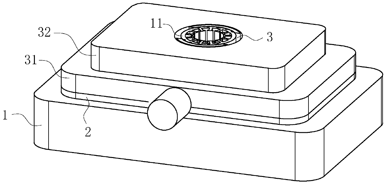
[0004] However, when the existing stamping tooling stamps the motor iron core, because the stamping workpiece 11 of the motor iron core has a circular structure, under the stamping force of the stamping device, the clamping contact surface of the stamping tooling to the stamping workpiece is too small. , which leads to the phenomenon of axial rotation of the stamping workpiece to be stamped, and at the same time causes the phenomenon of side tilting of the stamping workpiece, thereby reducing the stamping quality and stamping accuracy of the stamping workpiece

Method used


Image

  • Motor iron core stamping tool
  • Motor iron core stamping tool
  • Motor iron core stamping tool

Examples


Embodiment approach

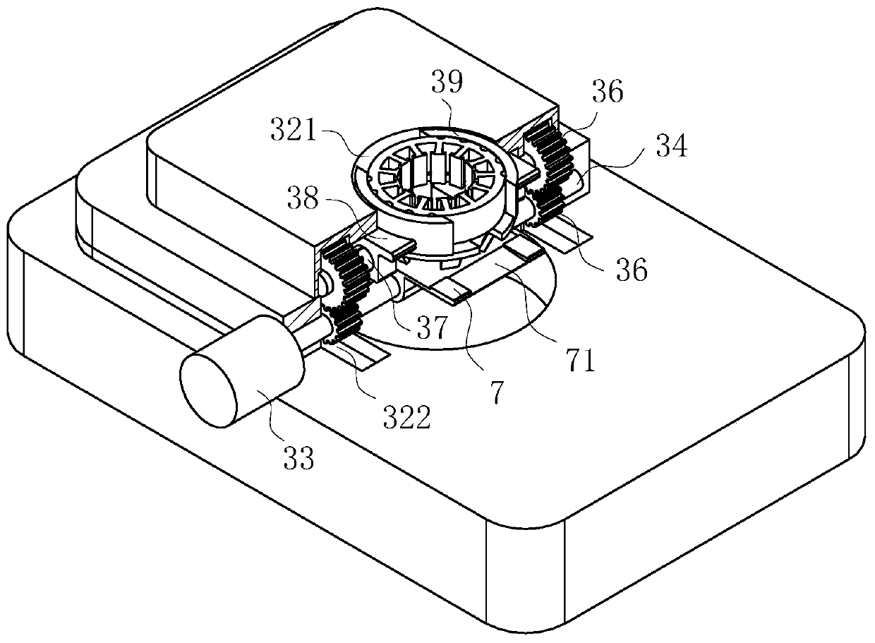
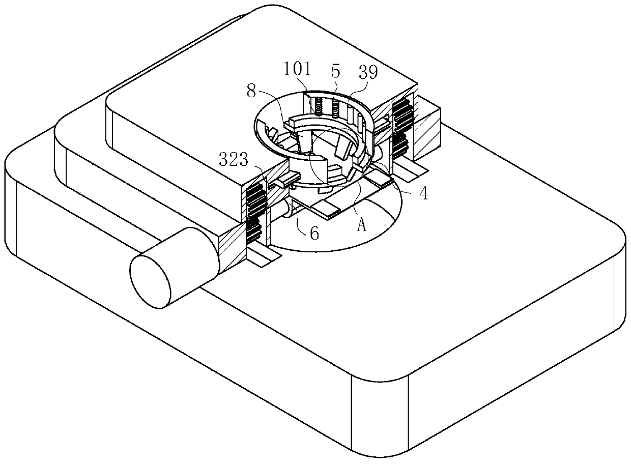
[0025] As an embodiment of the present invention, the inner wall of the curved splint 39 is vertically provided with an elastic wear-resistant strip 5, and the outer wall of the elastic wear-resistant strip 5 is provided with a corrugated layer; 11 When placed on the arc-shaped splint 39 and the arc-shaped support bar 4, the elastic wear-resistant strip 5 provided on the inner wall of the arc-shaped splint 39 is tightly attached to the outer wall of the stamping workpiece 11 under the extrusion force of the arc-shaped splint 39 Above, the elastic wear-resistant strip 5 can increase the clamping friction force between the arc splint 39 and the stamping workpiece 11, and at the same time increase the axial friction force between the stamping workpiece 11 and the arc splint 39, thereby reducing the stamping workpiece 11. The phenomenon of axial rotation deviation during stamping; at the same time, the rigid contact extrusion force between the stamping workpiece 11 and the arc spli...


PUM


Abstract

The invention belongs to the technical field of tool clamps, and particularly relates to a motor iron core stamping tool. The motor iron core stamping tool comprises a substrate; an electromagnetic plate is arranged above the substrate; a plane plate is mounted on the upper end face of the support panel; a driving motor is installed on the side surface of the support panel, and the output end of the driving motor penetrates through the support panel and is connected with a rotating shaft; the plane plate is provided with a mounting guide cavity, and a rotating shaft is rotationally mounted inthe mounting guide cavity; a driving gear is rotationally mounted in rotating cavities through a rotating shaft; driven gears are rotationally mounted above the rotating cavities through rotating columns; lead screw sliding blocks are slidably arranged on rotating lead screws in a sleeving and sliding mode, and the lead screw sliding blocks are slidably arranged in supporting sliding grooves formed in the side walls of the rotating cavities; arc-shaped clamping plates are fixed at the outer end parts of the lead screw sliding blocks, and the arc-shaped clamping plates are symmetrically arranged; and the bottom ends of the arc-shaped clamping plates are provided with arc-shaped supporting strips. The situation that axial rotation of a stamping workpiece to be stamped influences the stampingquality and the stamping precision of the stamping workpiece is effectively prevented.

Description

technical field [0001] The invention belongs to the technical field of jigs and fixtures, and in particular relates to stamping jigs for motor iron cores. Background technique [0002] The motor generally includes a casing with an inner cavity, and a stator and a rotor arranged in the inner cavity of the casing. The stator core of a conventional motor is made of stacked full-circle punches with tooth grooves, and then the winding work is performed. . [0003] The motor core is the core component of the motor, which is used to increase the magnetic flux of the inductance coil and realize the maximum conversion of electromagnetic power. Stamping is an important process step in the production process of the motor core. The workpiece to be processed is clamped on the lower die, and the upper die is connected to the driving device to stamp the workpiece on the lower die to form the required shape. Auxiliary tooling is usually required in stamping and forming. [0004] However,...

Claims


Application Information

Patent Timeline
Patent Type & Authority Applications(China)
IPC IPC(8): B21D43/00H02K15/02
CPCB21D43/003H02K15/02
Inventor 黄军刘进取吴贺
Owner 广州尚诚智能科技有限公司
Learn More