Eureka AIR delivers breakthrough ideas for toughest innovation challenges, trusted by R&D personnel around the world.

Oil heater assembly of separated oil circuit and electric heater

A separate and component-based technology, which is applied in the direction of central heating components, heating methods, electric heating systems, etc., can solve the problems of many welding processes, large heat transfer constraints of oil tanks, and large waste of space, so as to save volume and space. The effect of improving core competitiveness and good experience

Pending Publication Date: 2020-05-26
GREE ELECTRIC APPLIANCES INC
View PDF0 Cites 0 Cited by
  • Summary
  • Abstract
  • Description
  • Claims
  • Application Information

AI Technical Summary

Problems solved by technology

[0002] As a commonly used heating equipment, the electric heating oil heater occupies an important position in the electric heating product; therefore, it is of great significance to study the oil heater itself as an important heat dissipation and heat transfer device of the electric heating oil heater. At present, the mainstream electric heating oil heaters on the market are basically welded by sheet metal heaters, and the oil circuit is formed by the bead of the heater itself between the heater and the heater, and then heat is transferred through the oil through the oil circuit; this kind of heater Due to the limitation of the oil circuit, the waste of space is large, the heat dissipation and heat transfer of the oil tank are greatly restricted, and the manufacturing process is cumbersome, and there are many welding procedures; in view of this phenomenon, this design proposes a separate oil circuit for the oil circuit and the outer casing of the tank. Olein structure

Method used


Image

  • Oil heater assembly of separated oil circuit and electric heater
  • Oil heater assembly of separated oil circuit and electric heater
  • Oil heater assembly of separated oil circuit and electric heater

Examples


Embodiment Construction

[0022] In order to better understand the purpose, structure and function of the present invention, below in conjunction with appendix Figure 1-4 , understanding of the present invention.

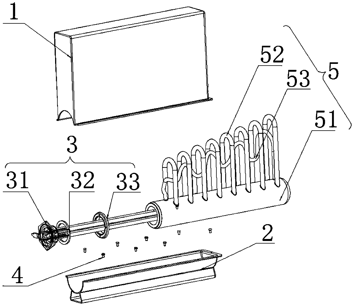
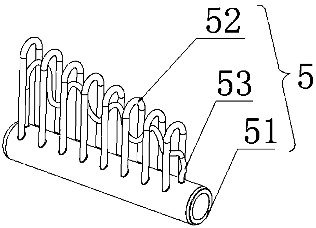
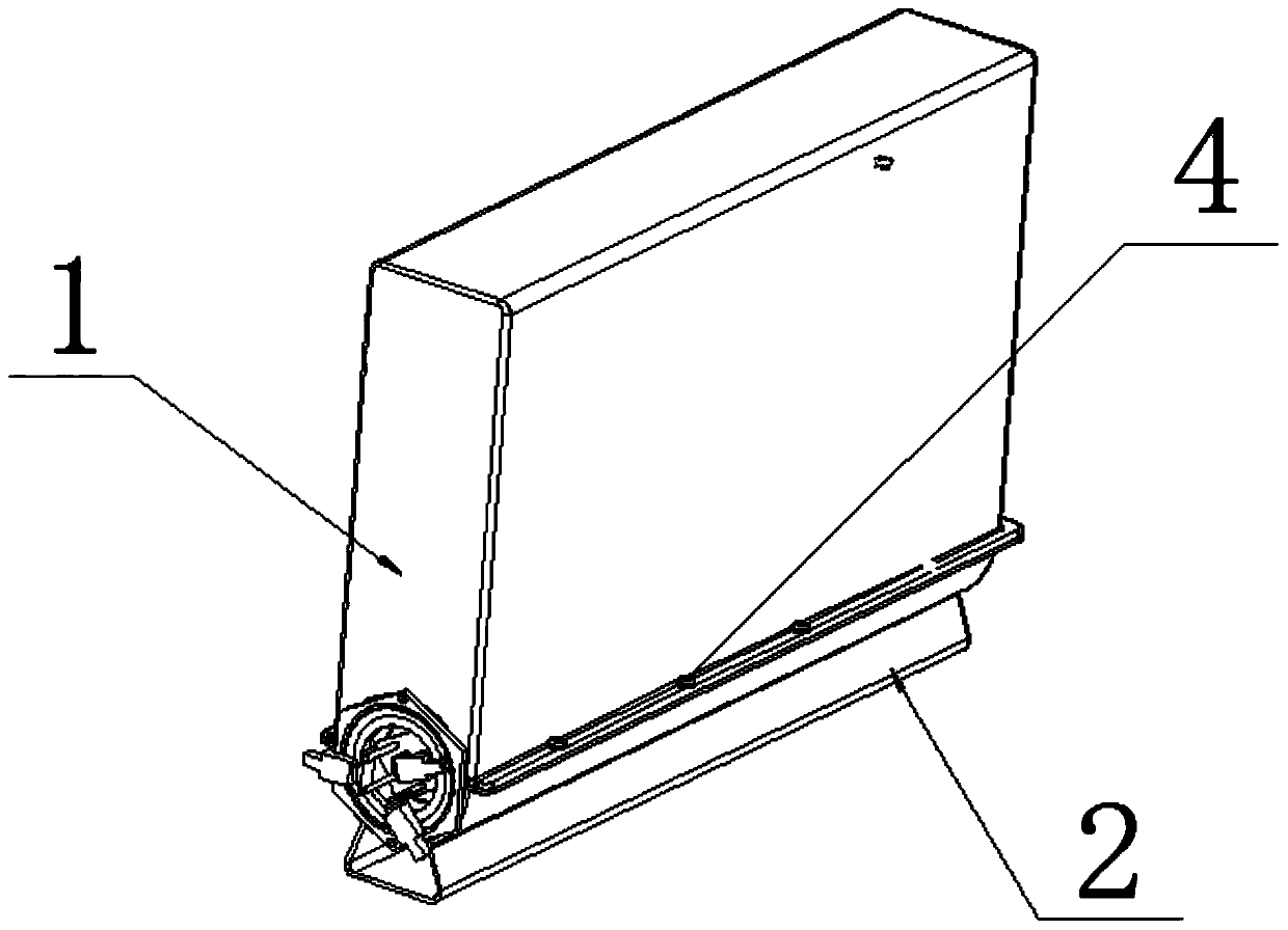
[0023] Such as figure 1 As shown, a separate oil circuit oil pump assembly is designed, including a casing, an oil storage assembly 5 arranged in the inner cavity of the casing, and a heating assembly 3 arranged in the oil storage assembly 5; wherein, the casing includes an upper cover 1 , bottom cover 2, fasteners, fasteners can choose screws 4, such as image 3 As shown, when the upper cover 1 and the bottom cover 2 are fastened to each other, the heating component 3 is stuck between the ends of the upper cover 1 and the bottom cover 2, so that the oil storage component 5 is fastened between the upper cover 1 and the bottom cover 2 In the cavity between them, screws 4 lock the upper cover 1 and the bottom cover 2 together.

[0024] The innovations of this design mainly lie in: figure...


PUM


Abstract

The invention discloses an oil heater assembly of a separated oil circuit. The oil heater assembly of the separated oil circuit comprises a shell, an oil storage assembly arranged in the inner cavityof the shell and a heating assembly arranged in the oil storage assembly; the oil storage assembly comprises oil storage tubes and an oil cylinder provided with the heating assembly, the outer side wall of the oil cylinder is connected with the multiple oil storage tubes in a penetrating mode, and thus the oil storage tubes are separated from the inner part of the oil cylinder; and the invention further discloses an electric heater, which comprises the oil heater assembly of the separated oil circuit. The design mainly solves the problem that a traditional oil heater oil circuit and a tablet are mixed together and cannot be separated; and by separating the oil storage tubes in the oil storage assembly, size space of the oil heater can be greatly saved, and at the same time, the structure trend of the oil circuit can be arranged more freely, so as to achieve the purpose of arrangement of the internal heat distribution in an oil heater body.

Description

technical field [0001] The invention belongs to the technical field of electrical appliances, and in particular relates to an oil heater assembly and an electric heater with a separated oil circuit. Background technique [0002] As a commonly used heating equipment, the electric heating oil heater occupies an important position in the electric heating product; therefore, it is of great significance to study the oil heater itself as an important heat dissipation and heat transfer device of the electric heating oil heater. At present, the mainstream electric heating oil heaters on the market are basically welded by sheet metal heaters, and the oil circuit is formed by the bead of the heater itself between the heater and the heater, and then heat is transferred through the oil through the oil circuit; this kind of heater Due to the limitation of the oil circuit, the waste of space is large, the heat dissipation and heat transfer of the oil tank are greatly restricted, and the m...

Claims


Application Information

Patent Timeline
IPC IPC(8): F24D13/04F24D19/00
CPCF24D13/04F24D19/00F24D2200/08F24D2220/2036
Inventor 陈影炙廖泓斌张毅白相星唐爱红衷卫健
Owner GREE ELECTRIC APPLIANCES INC
Why Eureka
Eureka Blog
Learn More