
Distributed electric propulsion tilt rotor unmanned aerial vehicle

An unmanned aerial vehicle and tilt-rotor technology, which is applied in the field of distributed electric propulsion tilt-rotor unmanned aerial vehicles, can solve the problems of heavy aircraft, fixed-wing unable to take off and land vertically, and small flight time and range of rotorcraft.

Inactive Publication Date: 2020-05-26
湖北航天飞行器研究所
View PDF6 Cites 6 Cited by
  • Summary
  • Abstract
  • Description
  • Claims
  • Application Information

AI Technical Summary

Problems solved by technology

[0005] Aiming at the problems that conventional fixed wings cannot take off and land vertically and hover in the air, the flight time of rotorcraft is small, and the "dead weight" of compound vertical takeoff and landing aircraft is more, this patent provides a distributed electric propulsion tiltrotor unmanned aerial vehicle The solution can realize vertical take-off and landing, fixed-point hovering in the air and high-efficiency cruising and level flight

Method used


Image

  • Distributed electric propulsion tilt rotor unmanned aerial vehicle
  • Distributed electric propulsion tilt rotor unmanned aerial vehicle
  • Distributed electric propulsion tilt rotor unmanned aerial vehicle

Examples


Embodiment Construction

[0015] In order to make the object, technical solution and advantages of the present invention clearer, the present invention will be further described in detail below in conjunction with the accompanying drawings and specific embodiments. It should be understood that the specific embodiments described here are only used to explain the present invention, not to limit the present invention. In addition, the technical features involved in the various embodiments of the present invention described below can be combined with each other as long as they do not constitute a conflict with each other.

[0016] A specific technical solution adopted by the patent of the present invention is: a distributed electric propulsion tilt-rotor unmanned aerial vehicle, including a structural system, a power system, a flight control system and an avionics system.

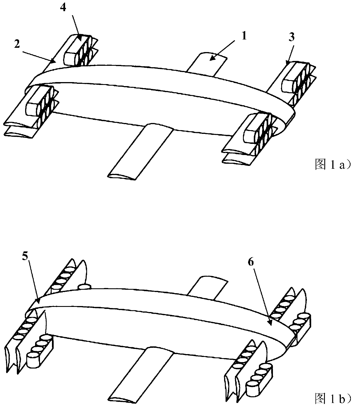
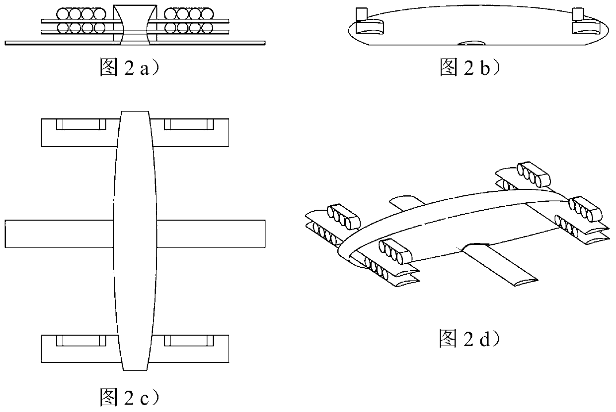
[0017] Such as figure 1 As shown, the structural system includes fuselage and wings. Three sections of wings are arranged on the fus...


PUM


Abstract

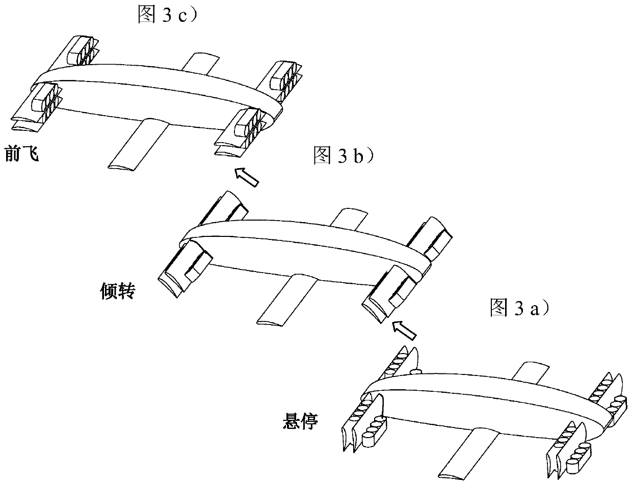
The invention discloses a distributed electric propulsion tilt rotor unmanned aerial vehicle. According to the aircraft, a three-section fixed type wing overall layout is adopted; front wings and rearwings are arranged in two layers; the wings in the upper and lower layer are each provided with electric propulsion ducted fans; a middle wing is mainly used for generating lift force when fixed wings fly; the ducted fans serve as a power system, and thrust generated by the ducted fans is used for achieving the vertical take-off and landing, hovering and fixed wing patrolling of the aircraft; tilting mechanisms are arranged at the joints of the front wings, the rear wings and an aircraft body so as to achieve mutual switching between a vertical take-off & landing and hovering mode and a fixedwing patrolling mode. When the aircraft has the speed required for patrol flight, transition from the vertical take-off & landing and hovering mode to the fixed wing mode is completed. According to the distributed electric propulsion tilt rotor unmanned aerial vehicle of the invention, the distributed electric propulsion ducted fans are adopted as the aircraft power system, and therefore, the size and weight of the power system are reduced, the redundancy and reliability of the power system are improved; and a ducted fan rotating speed differential mode is adopted during fixed wing patrollingflight, so that control efficiency can be improved.

Description

technical field [0001] The invention belongs to the general technical field of unmanned aerial vehicles, and in particular relates to a distributed electric propulsion tilt-rotor unmanned aerial vehicle. Background technique [0002] Traditional unmanned aerial vehicles can be divided into two types: fixed-wing and rotary-wing aircraft. When the fixed-wing aircraft is flying, the power system generates forward thrust, and the wings generate the required lift to offset its own gravity, and the flight time and range are relatively large; its take-off methods can be divided into hand throwing, ejection, sliding, etc., and landing and recovery can be achieved by hitting the net , parachuting, sliding and other methods. The take-off and landing conditions of fixed-wing aircraft are relatively high. A flat runway is required for taxi take-off or landing. A special ejection device is required for catapult take-off. Hand-throwing requires personnel with rich operating experience. ...

Claims


Application Information

Patent Timeline
IPC IPC(8): B64C3/20B64C11/46B64D27/24
CPCB64C3/20B64C11/46B64D27/24B64U10/00B64U50/19Y02T50/60Y02T50/40
Inventor 李康伟黄晓龙李盛周子鸣邬华明张达刘青张华君
Owner 湖北航天飞行器研究所
Learn More