
Assembling and welding manufacturing process of large pressure vessel

A pressure vessel and manufacturing process technology, which is applied in the field of large-scale pressure vessel assembly and welding manufacturing process, can solve the problems of position deviation, end cap offset, and heavy weight after welding of end caps, so as to avoid position deviation, improve accuracy, and improve quality effect

Inactive Publication Date: 2020-05-26
潘军
View PDF0 Cites 1 Cited by
  • Summary
  • Abstract
  • Description
  • Claims
  • Application Information

AI Technical Summary

Problems solved by technology

[0004] The invention provides a large-scale pressure vessel assembly and welding manufacturing process, aiming to solve the following problems existing in the current welding of large-scale pressure vessel end caps and cylinders: (1) The end caps of large-scale pressure vessels are relatively large in volume and heavy in weight , and the inner and outer surfaces of the end cover are arc surfaces, it is difficult to firmly support the end cover during the welding process, and the end cover is prone to offset along the radial direction of the cylinder, resulting in position deviation of the end cover after welding; (2) due to The side wall of a large pressure vessel is relatively thick, and a certain weld seam needs to be left between the end cover and the cylinder to ensure the welding strength; during the welding process, the end cover is prone to offset along the cylinder axis, resulting in the The uneven width of the weld seam will cause the position deviation of the end cover after welding, and it will also have an adverse effect on the overall strength of the large pressure vessel

Method used


Image

  • Assembling and welding manufacturing process of large pressure vessel
  • Assembling and welding manufacturing process of large pressure vessel
  • Assembling and welding manufacturing process of large pressure vessel

Examples


Embodiment Construction

[0037] The embodiments of the present invention are described in detail below with reference to the accompanying drawings, but the present invention can be implemented in many different ways as defined and covered by the claims.

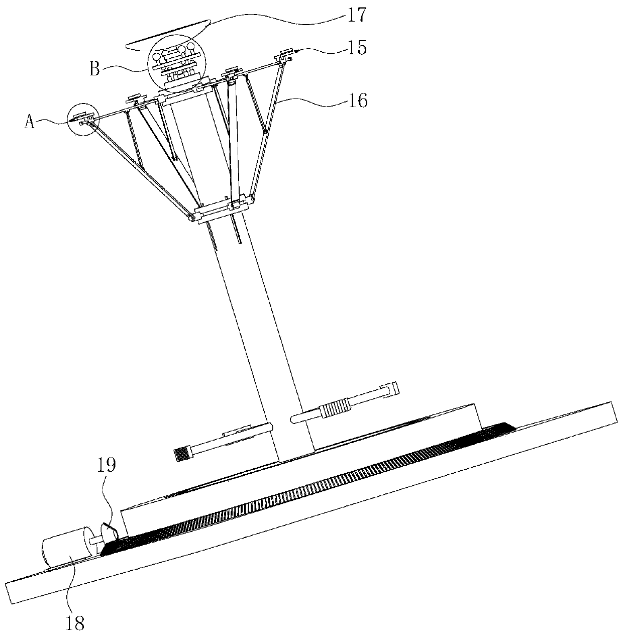
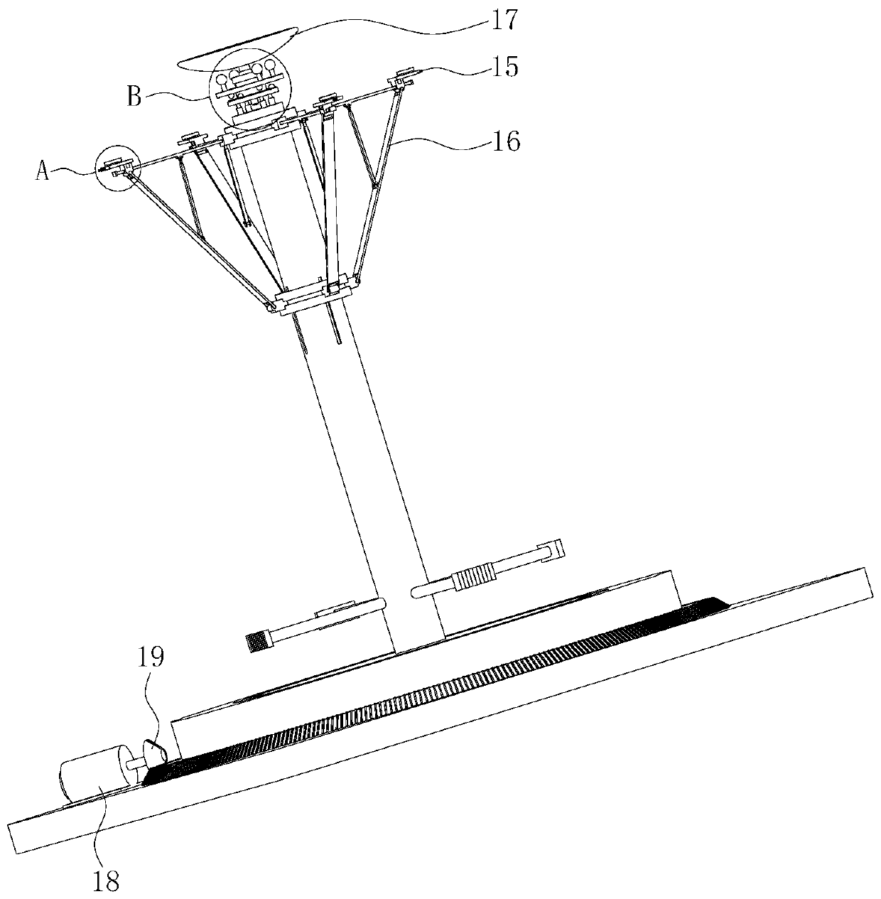
[0038] like Figure 1 to Figure 8 As shown, this embodiment provides a large-scale pressure vessel assembly and welding manufacturing machine, including a horizontally arranged bottom plate 1, a turntable 2 is installed horizontally on the upper surface of the bottom plate 1, and a base 3 is fixedly installed on the upper surface of the turntable 2. The upper surface of the base 3 is provided with an annular groove 4 which cooperates with the cylinder of the pressure vessel. The upper surface of the base 3 is located at the center of the annular groove 4 and is vertically and fixedly connected with a mounting column 5 .

[0039] A sliding slot 6 is vertically opened on the mounting column 5 , and an electric sliding sleeve 7 matched with the outer s...


PUM


Abstract

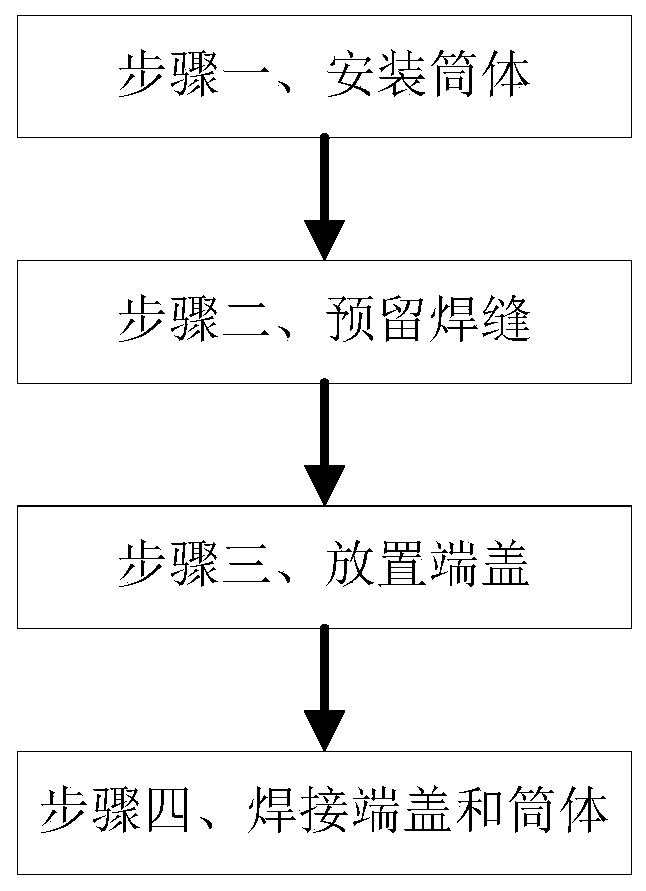
The invention belongs to the technical field of pressure vessels, and in particular relates to an assembling and welding manufacturing process of a large pressure vessel, which is completed through the cooperation with an assembling and welding manufacturing machine for a large pressure vessel. The assembling and welding manufacturing process specifically comprises the following steps of Step 1, mounting a cylinder: inserting the bottom end of the cylinder into an annular groove; Step 2, reserving a welding seam: driving a mounting block to slide through an electric sliding sleeve until a first supporting mechanism reaches a position above the top surface of the cylinder; Step 3, placing an end cap: hanging the end cap on a second supporting mechanism, and supporting the end cover by the first supporting mechanism and the second supporting mechanism; and Step 4, welding the end cover and the cylinder: driving the cylinder to rotate through a base, and welding along the end cover and the edge of the cylinder by a welding gun. When the end cap and the cylinder of the large pressure vessel are welded, the radial and axial deviation of the end cover during the welding process is avoided, and the accuracy of the end cap welding position is improved.

Description

technical field [0001] The invention belongs to the technical field of pressure vessels, and in particular relates to a large-scale pressure vessel assembly and welding manufacturing process. Background technique [0002] A pressure vessel is a closed device that contains gas or liquid and carries a certain pressure. Pressure vessels are widely used, mainly used for heat transfer, mass transfer, reaction and other processes, as well as storage and transportation of pressurized gas or liquefied gas; has an important position and role. When assembling a large pressure vessel, the end cap needs to be welded to the cylinder body. The method used is to first butt the end cap and the cylinder body and fix the end cap and the cylinder body, and then use the welding torch to follow the seam between the end cap and the cylinder body. For welding, in the actual production process, this method has the following problems: (1) The end caps of large pressure vessels are large in volume ...

Claims


Application Information

Patent Timeline
Patent Type & Authority Applications(China)
IPC IPC(8): B23K37/00B23K37/047
CPCB23K37/00B23K37/047
Inventor 潘军张国华
Owner 潘军
Learn More