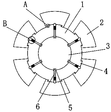
Built-in tangential rotor magnetic pole structure

A technology of rotor magnetic poles and magnetic pole cores, which is applied in the field of built-in tangential rotor magnetic pole structures, can solve problems such as core damage and economic loss, and achieve the effect of preventing axial deviation

Inactive Publication Date: 2019-03-22
山东迈易特传动有限公司
View PDF1 Cites 1 Cited by
  • Summary
  • Abstract
  • Description
  • Claims
  • Application Information

AI Technical Summary

Problems solved by technology

[0004] However, after the yoke sleeve and the pole core are matched, the final positioning is fixed and limited by pins. However, the pins need to be pulled out forcibly when they are removed, maintained and replaced in the later stage. However, due to the magnetic properties of the pole core, the material Particularity, the traditional forced demolition method is likely to cause damage to the iron core, resulting in economic losses

Method used


Image

  • Built-in tangential rotor magnetic pole structure
  • Built-in tangential rotor magnetic pole structure
  • Built-in tangential rotor magnetic pole structure

Examples


Embodiment Construction

[0020] The following will clearly and completely describe the technical solutions in the embodiments of the present invention with reference to the accompanying drawings in the embodiments of the present invention. Obviously, the described embodiments are only some, not all, embodiments of the present invention.

[0021] In describing the present invention, it should be understood that the terms "upper", "lower", "front", "rear", "left", "right", "top", "bottom", "inner", " The orientation or positional relationship indicated by "outside", etc. is based on the orientation or positional relationship shown in the drawings, and is only for the convenience of describing the present invention and simplifying the description, rather than indicating or implying that the referred device or element must have a specific orientation, so as to Specific orientation configurations and operations, therefore, are not to be construed as limitations on the invention.

[0022] refer to Figure ...


PUM


Abstract

The invention discloses a built-in tangential rotor magnetic pole structure. The built-in tangential rotor magnetic pole structure comprises a magnetic yoke sleeve and a plurality of magnetic pole cores; the magnetic yoke sleeve is provided with a plurality of tenon strips; the plurality of magnetic pole cores are in one-to-one correspondence with the plurality of tenon strips; the tenon grooves are formed in each of the magnetic pole cores respectively; the tenon grooves are matched with the tenon strips; a central hole is formed in the magnetic yoke sleeve; a plurality of inner hexagon adjusting screw rods are in threaded connection with the interior of the magnetic yoke sleeve; a plurality of spring grooves are formed in the magnetic yoke sleeve; an elastic mechanism is arranged in eachspring groove; and arc-shaped pins are slidably connected into the spring grooves respectively. According to the built-in tangential rotor magnetic pole structure of the present invention, when the arc-shaped pins are not restricted, a soft tool such as a rubber hammer is adopted to lightly tap the magnetic pole cores, so that the side walls of arc-shaped grooves press the arc-shaped pins so as to make the arc-shaped pins retreat into the spring grooves until the magnetic pole cores escape from the magnetic yoke sleeve and the tenon strips are separated from the tenon grooves, and an entire disassembling process is completed; and the whole process is more stable and safer, and will not damage the magnetic pole cores.

Description

technical field [0001] The invention relates to the technical field of rotor poles, in particular to a built-in tangential rotor pole structure. Background technique [0002] In the induction motor, the rotor, which is composed of a rotating shaft core and a closed conductor embedded in the core, generates high-speed rotary motion under the drive of the rotating magnetic field generated by the stator winding. Both ends of the rotor adopt rolling bearings and are installed and fixed in the end cover of the motor casing. [0003] According to Chinese patent: CN202696304U, a solid rotor pole structure, including: a pole core and a yoke sleeve, wherein the pole core is installed on the outer surface of the yoke sleeve, and the pole core and the yoke sleeve are passed through each other The axial groove and the protruding part on the contact surface are fixed. The axial groove and the protruding part have matching shapes. This structure can solve the magnetic The original conne...

Claims


Application Information

Patent Timeline
Patent Type & Authority Applications(China)
IPC IPC(8): H02K1/22H02K1/28
CPCH02K1/22H02K1/28
Inventor 尹超张传昌孙少男岳宁刘德军刘冰白东海
Owner 山东迈易特传动有限公司
Why Eureka
Try Eureka