Automatic cleaning device applied to beam-pumping unit and working method of automatic cleaning device

A beam pumping unit, automatic cleaning technology, applied to the cleaning method using liquid, cleaning method using tools, cleaning methods and utensils, etc., can solve the inconvenience of beam pumping unit cleaning, can not adjust the beam at the same time Problems such as beam pumping unit and cleaning device, to achieve the effect of reducing storage space

Inactive Publication Date: 2020-05-26
赵琢萍
View PDF0 Cites 0 Cited by
  • Summary
  • Abstract
  • Description
  • Claims
  • Application Information

AI Technical Summary

Problems solved by technology

[0003] The object of the present invention is to provide a kind of automatic cleaning device and its working method applied to the beam pumping unit, to solve the inconvenience proposed in the above-mentioned background technology, when the beam pumping unit can only be cleaned on one side Cleaning and not being able to adjust the position of the beam pumping unit and the cleaning device at the same time to realize the cleaning of the beam pumping unit

Method used


Image

  • Automatic cleaning device applied to beam-pumping unit and working method of automatic cleaning device
  • Automatic cleaning device applied to beam-pumping unit and working method of automatic cleaning device
  • Automatic cleaning device applied to beam-pumping unit and working method of automatic cleaning device

Examples


Embodiment Construction

[0052] The following will clearly and completely describe the technical solutions in the embodiments of the present invention with reference to the accompanying drawings in the embodiments of the present invention. Obviously, the described embodiments are only some, not all, embodiments of the present invention. Based on the embodiments of the present invention, all other embodiments obtained by persons of ordinary skill in the art without making creative efforts belong to the protection scope of the present invention.

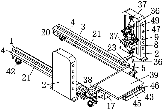
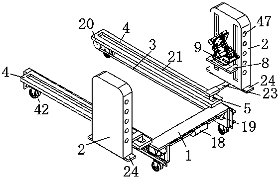
[0053] see Figure 1-12 , in an embodiment of the present invention, an automatic cleaning device applied to a beam pumping unit, comprising a U-shaped bottom plate 1, a moving plate 2 and a cleaning mechanism;

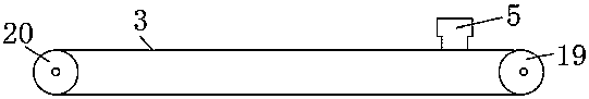
[0054] The left and right inner walls of the U-shaped bottom plate 1 are connected with a belt 3 through transmission, the left and right inner walls of the U-shaped bottom plate 1 are fixedly connected with a fixed plate 4, the fixed plate 4 is slida...


PUM


Abstract

The invention discloses an automatic cleaning device applied to a beam-pumping unit and a working method of the automatic cleaning device. The automatic cleaning device comprises a U-shaped bottom plate, a movable plate and a cleaning mechanism, wherein belts are in transmission connection with the left inner side wall and the right inner side wall of the U-shaped bottom plate, fixing plates are fixedly connected with the left inner side wall and the right inner side wall of the U-shaped bottom plate, sliding blocks are connected to the fixing plates in a sliding mode, the lower ends of the sliding blocks are fixedly connected to the belts, the upper ends of the sliding blocks are movably connected with moving plates, cavities are formed in the inner side walls of the moving plates, sliding plates are connected into the cavities in an up-down sliding mode, connecting blocks are symmetrically and fixedly connected to the sliding plates, and one ends of the connecting blocks penetrate through the side walls of the cavities and are fixedly connected with connecting plates. According to the automatic cleaning device applied to the beam-pumping unit and the working method of the automatic cleaning device, when in use, cleaning work of the beam-pumping unit is conveniently achieved, and when the device is not used, the storage space of the device is reduced.

Description

technical field [0001] The invention relates to the technical field of cleaning equipment for a beam pumping unit, in particular to an automatic cleaning device applied to a beam pumping unit and a working method thereof. Background technique [0002] Beam pumping unit, also known as beam pumping unit and beam pumping unit with crank balance, refers to a pumping unit that contains a beam, reverses direction through a connecting rod mechanism, and balances crank weights, commonly known as a kowtow machine. When working, the transmission of the motor becomes the up and down movement of the donkey head through the gearbox and the crank connecting rod mechanism, and the donkey head drives the plunger of the downhole oil well pump to move up and down through the polished rod and the sucker rod, so that the crude oil in the well is continuously pumped out of the wellbore , After the beam pumping unit is used, it needs to be cleaned to keep the beam pumping unit clean and prevent t...

Claims


Application Information

Patent Timeline
IPC IPC(8): B08B1/04B08B3/02B08B13/00
CPCB08B3/02B08B13/00B08B1/32B08B1/12
Inventor 赵琢萍彭灵孙刚蔚贝贝石健袁辉赵紫妤张晨张川刘鑫梅王皓
Owner 赵琢萍
Why Eureka
Try Eureka