Laser remote foreign matter removing instrument and using method thereof
A foreign matter removal and remote technology, applied in the direction of overhead line/cable equipment, etc., can solve the problems of human and livestock casualties, short circuit of transmission lines, etc., and achieve the effect of high efficiency removal, small size and simple structure
- Summary
- Abstract
- Description
- Claims
- Application Information
AI Technical Summary
Problems solved by technology
Method used
Image
Examples
Embodiment 1
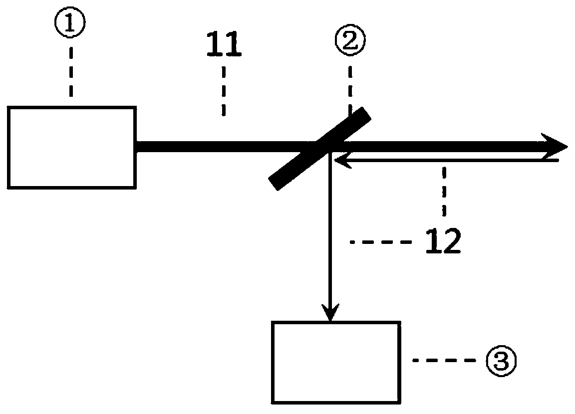
[0041] The present invention is realized through the following technical solutions, as figure 1 As shown, a laser remote foreign matter removal instrument includes a laser 1, a beam splitter 2, and a target imaging module 3. The laser 1 is used to emit a laser beam 11 to the beam splitter 2, and the beam splitter 2 transmits the received laser beam 11 After that, it is emitted to the target foreign object, and the target light 12 reflected by the target foreign object is visible light. The target light 12 is reflected by the beam splitter 2 and enters the target imaging module 3 to form a target image in the target imaging module 3 .
[0042] The present invention emits the laser beam 11 generated by the laser 1 on the target foreign matter, forms a high-power-density laser spot on the target foreign matter, and realizes the removal of the target foreign matter by means of melting or burning. The laser beam 11 generated by the cleaning device is usually invisible to the human ...
Embodiment 2
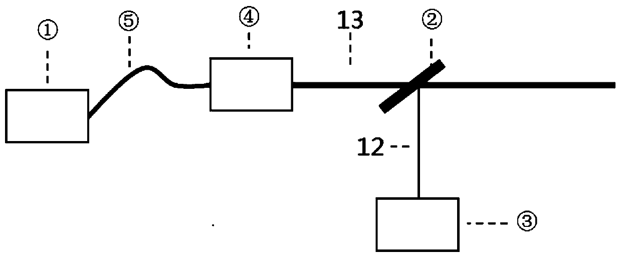
[0047] This embodiment is further optimized on the basis of the above-mentioned embodiment 1, such as figure 2 As shown, the collimating and focusing module 4 is arranged on the side of the beam splitter 2 close to the laser 1, and the laser 1 and the collimating and focusing module 4 are connected by an optical fiber 5, and the optical fiber 5 transmits the laser beam 11 generated by the laser 1 to the collimating and adjusting module The focus module 4, the collimating and focusing module 4 optically transforms the laser beam 11 input by the optical fiber 5 and outputs it as a collimated laser beam 13, or adjusts the collimating and focusing module 4 manually or automatically as required to output a certain A collimated laser beam 13 at a focal length. The collimated laser beam 13 passes through the beam splitter 2 and shoots to the target foreign object, and the target light 12 reflected from the target foreign object is reversely transmitted to the beam splitter 2 along t...
Embodiment 3
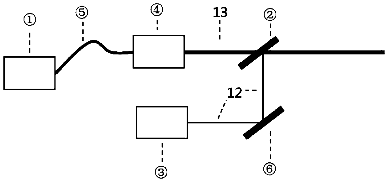
[0050] This embodiment is further optimized on the basis of the above-mentioned embodiment 1, such as image 3 As shown, a mirror 6 is added between the beam splitter 2 and the target imaging module 3, and the target imaging module 3 is arranged in parallel with the collimation and focusing module 4, and the target light 12 reflected from the beam splitter 2 passes through the mirror After the reflection of 6, enter the target imaging module 3 again. In this embodiment, since the target imaging module 3 is placed in parallel with the collimating and focusing module 4, the distance of the clearing instrument in the direction perpendicular to the optical axis of the emitted laser beam 11 is reduced. size. Adjust the setting position and angle of the beam splitter 2 and the reflector 6 according to the actual usage, so that the target light 12 from the target foreign object can enter the target imaging module 3 after being reflected by the beam splitter 2 and the reflector 6, and...
PUM
 Abstract
Description
Claims
Application Information
 - R&D
- Intellectual Property
- Life Sciences
- Materials
- Tech Scout
- Unparalleled Data Quality
- Higher Quality Content
- 60% Fewer Hallucinations
Browse by: Latest US Patents, China's latest patents, Technical Efficacy Thesaurus, Application Domain, Technology Topic, Popular Technical Reports.
© 2025 PatSnap. All rights reserved.Legal|Privacy policy|Modern Slavery Act Transparency Statement|Sitemap|About US| Contact US: help@patsnap.com


