
A Measuring Device for Machine Tool Geometric Error Based on the Principle of Laser Interferometry

A technology of laser interference and geometric error, applied in mechanical measuring devices, measuring devices, using mechanical devices, etc., can solve the problems of high measurement cost, time-consuming, laborious, and expensive, and achieve flexible device movement, simple operation, and high satisfaction. The effect of precision measurement

Active Publication Date: 2021-08-10
西安阿贝铟精密仪器有限公司
View PDF26 Cites 0 Cited by
  • Summary
  • Abstract
  • Description
  • Claims
  • Application Information

AI Technical Summary

Problems solved by technology

[0002] The current geometric error measurement of machine tools includes laser tracker, laser interferometer and other instruments. Although the laser tracker has timeliness in operation and measurement, it is expensive and the measurement cost is too high; while the laser interferometer measurement has high accuracy. , but measuring each error requires rebuilding the optical path, which is time-consuming and labor-intensive

Method used


Image

  • A Measuring Device for Machine Tool Geometric Error Based on the Principle of Laser Interferometry
  • A Measuring Device for Machine Tool Geometric Error Based on the Principle of Laser Interferometry
  • A Measuring Device for Machine Tool Geometric Error Based on the Principle of Laser Interferometry

Examples


Embodiment Construction

[0031] The present invention will be described in further detail below in conjunction with the accompanying drawings.

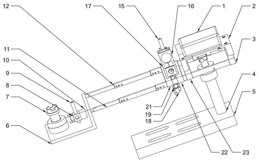
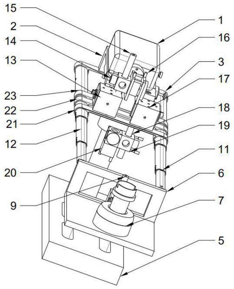
[0032] refer to figure 1 , figure 2 , a machine tool geometric error measuring device based on the principle of laser interference, including a mechanical tracking device and a laser measuring device installed on it;

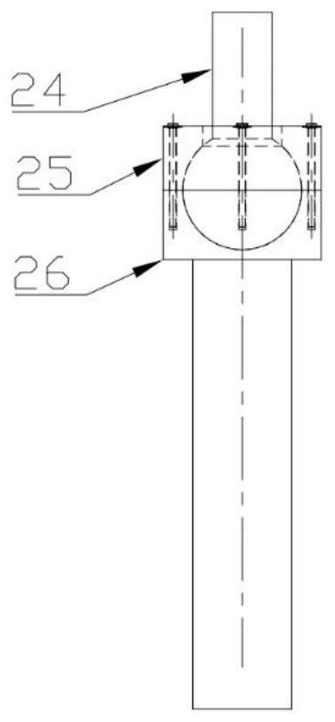
[0033] The mechanical tracking device includes a laser interferometer 1, the laser interferometer 1 is fixed on the interferometer adjustment platform 2 through threaded connection, the bottom of the interferometer adjustment platform 2 is connected with the work billiard ball hinge 4, and the bottom of the work billiard ball hinge 4 Installed on the machine tool connection platform 5; the interferometer adjustment platform 2 is fixed on the upper mounting base 3 and the lower mounting base 3 23, and the upper mounting base 3 and the lower mounting base 23 are inserted into the first telescopic rod 11 and the second telescopic rod 12, and use...


PUM


Abstract

A machine tool geometric error measuring device based on the principle of laser interferometry, including a mechanical tracking device and a laser measuring device installed on it; the mechanical tracking device includes a laser interferometer, and the laser interferometer adjusts the hinge connection between the platform and the table ball through the interferometer, and works The bottom of the billiard hinge is installed on the connecting platform of the machine tool; the interferometer carrying platform is installed on the telescopic rods 1 and 2 connected by the upper mount 1 and the lower mount 3 at the same time, and the connecting plate at the end of the telescopic rod is installed with a ball hinge at the cutter head With the linear mirror, the first and second lower mounts on the telescopic rod are equipped with a fixed rotating mirror and a linear interference mirror group; the present invention increases the range of the laser interferometer through the telescopic rod, and provides guarantee for the spatial attitude adjustment of the laser interferometer through the ball hinge , effectively improve the measurement efficiency of the geometric error of the CNC machining center, and realize the automation of measurement through computer cooperative processing of measurement data, which has the advantages of flexible movement, simple operation and efficient measurement.

Description

technical field [0001] The invention relates to the technical field of machine tool geometric error measurement, in particular to a machine tool geometric error measurement device based on the principle of laser interference. Background technique [0002] The current geometric error measurement of machine tools includes laser tracker, laser interferometer and other instruments. Although the laser tracker is time-sensitive in operation and measurement, it is expensive and the measurement cost is too high; while the laser interferometer measurement has high accuracy. , but measuring each error requires rebuilding the optical path, which is time-consuming and laborious. Contents of the invention [0003] In order to overcome the shortcomings of the above-mentioned prior art, the purpose of the present invention is to provide a machine tool geometric error measurement device based on the principle of laser interference, which can effectively improve the measurement efficiency ...

Claims


Application Information

Patent Timeline
Patent Type & Authority Patents(China)
IPC IPC(8): G01B11/00
CPCG01B5/0004G01B11/00
Inventor 李海涛
Owner 西安阿贝铟精密仪器有限公司
Learn More