
Floor thickness measuring device

A technology of thickness measurement and floor slab, applied in the direction of mechanical thickness measurement, etc., can solve the problems of high labor cost, low cost, high cost, etc., and achieve the effect of simple structure, easy use, and reduced labor cost

Pending Publication Date: 2020-05-22
福建方实工程检测有限公司
View PDF0 Cites 2 Cited by
  • Summary
  • Abstract
  • Description
  • Claims
  • Application Information

AI Technical Summary

Problems solved by technology

[0002] In the construction inspection and acceptance process of construction projects, in order to ensure that the thickness of the floor slab meets the design and specification requirements, it is necessary to measure the thickness of the floor slab. In the prior art, there are two detection methods, one is to use a special floor slab thickness measurement This type of floor thickness gauge uses the principle of electromagnetic wave kinematics to indirectly measure the thickness of concrete structures and other non-metallic and magnetic media according to the distribution characteristics of electromagnetic fields. The measurement results are accurate, but the cost is high and the weight is heavy. There are certain limitations in handling and use; the other is the traditional use of measuring rulers for detection, although the measurement accuracy is reduced, but it is easy to carry and the cost is low, so it is more widely used
[0003] When a measuring ruler is used for detection, a measuring hole is usually opened on the floor. When measuring, a worker needs to climb up, abut the abutment part of the measuring ruler against the bottom of the floor, and pass the scale part of the measuring ruler through measuring hole, another worker is on the top surface of the floor, after the scale part of the measuring ruler passes through the measuring hole, the reading is taken. However, using this measurement method requires at least two workers to complete the measurement, and one of them One worker also needs to climb above the floor to take readings, resulting in high labor costs when using this method, so it needs to be improved

Method used


Image

  • Floor thickness measuring device
  • Floor thickness measuring device
  • Floor thickness measuring device

Examples


Embodiment 2

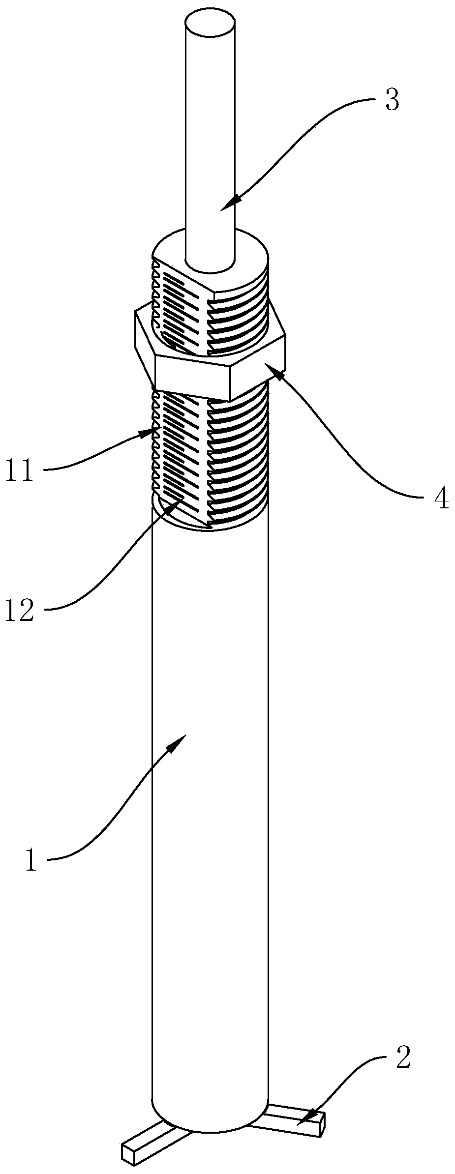
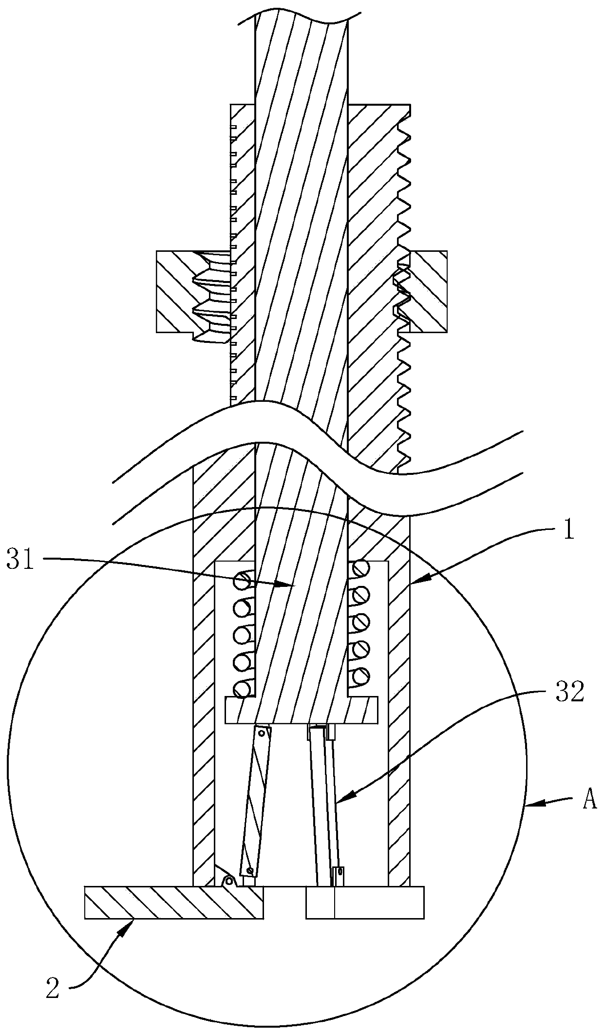
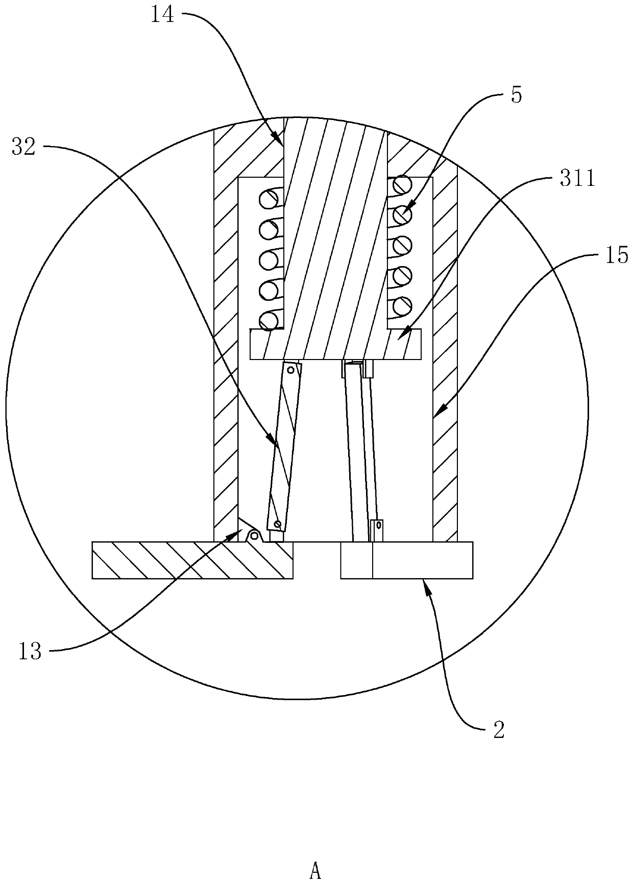
[0044] to combine Figure 4 and Figure 5 As shown, the difference from Embodiment 1 is that in Embodiment 2, the outer cylinder rod 1 is provided with an opening at one end of the limit card 2, and the driving mechanism 3 includes a Out of the outer cylinder rod 1 to drive each piece of limit card 2 toward the direction away from the axis of the outer cylinder rod 1 The driving rod 31 and several pieces are sleeved on each piece of limit card 2 and extend into the outer cylinder rod 1 One end is used to drive the first spring 22 that is used to drive each piece of the limit card 2 towards the direction close to the axis of the outer cylinder rod 1; wherein, combined with Figure 6 As shown, a plurality of slots 16 are arranged on the outer wall of the lower end of the outer cylinder rod 1, and each limit card 2 is inserted into each slot 16 respectively, and each limit card 2 is close to one end of the axis of the outer cylinder rod 1 The outer wall of the ring limit card 2...


PUM


Abstract

The invention relates to a floor thickness measuring device, and relates to the floor detection device technical field. The floor thickness measuring device comprises an outer cylinder rod, a plurality of limiting clamps and a driving mechanism, wherein scale marks are arranged on the outer wall of the outer cylinder rod, the limiting clamps are arranged at one end of the outer cylinder rod and are used for limiting the insertion depth of the outer cylinder rod, and the driving mechanism is inserted into the outer cylinder rod, is linked with the limiting clamps and is used for driving the limiting clamps to be folded or unfolded; scale marks are arranged on the outer wall of the outer cylinder rod, and the outer wall of the outer cylinder rod is further in threaded connection with a positioning nut used for identifying the position. The floor thickness measuring device has the effect of being convenient to use.

Description

technical field [0001] The invention relates to the technical field of floor detection devices, in particular to a floor thickness measurement device. Background technique [0002] In the construction inspection and acceptance process of construction projects, in order to ensure that the thickness of the floor slab meets the design and specification requirements, it is necessary to measure the thickness of the floor slab. In the prior art, there are two detection methods, one is to use a special floor slab thickness measurement This type of floor thickness gauge uses the principle of electromagnetic wave kinematics to indirectly measure the thickness of concrete structures and other non-metallic and magnetic media according to the distribution characteristics of electromagnetic fields. The measurement results are accurate, but the cost is high and the weight is heavy. There are certain limitations in handling and use; the other is the traditional use of a measuring ruler for...

Claims


Application Information

Patent Timeline
IPC IPC(8): G01B5/06
CPCG01B5/06
Inventor 刘昊李志超
Owner 福建方实工程检测有限公司
Learn More