
Self-balancing lifting device and control method thereof

A technology of lifting device and control method, which is applied in the direction of lifting equipment, transportation and packaging in mines, can solve the problems of limitation, large space occupation, overweight, etc., and achieve high feasibility, low power demand and small space occupation Effect

Pending Publication Date: 2020-05-22
HEBEI KELI AUTOMOBILE EQUIP CO LTD
View PDF1 Cites 0 Cited by
  • Summary
  • Abstract
  • Description
  • Claims
  • Application Information

AI Technical Summary

Problems solved by technology

The counterweight arm, load arm and counterweight weight of the existing lifting device are often unchanged, the load that the counterweight can balance is limited, and the power demand for the electric motor or hydraulic motor is relatively high
In addition, when the equipment starts or brakes, the counterweight and load will be overweight or lose weight. At this time, the rotating shaft will bear a large starting or braking torque, and at the same time, it will impact the motor or hydraulic motor, making the rotating shaft , motor or hydraulic motor torque overload, and even cause serious safety accidents
[0003] CN 105645242 A provides an elevator intelligent counterweight system, which adds a set of counterweights outside the main counterweight, and balances the load weight by increasing or reducing the number of counterweights loaded on the wire rope, but the counterweight The weight is fixed, and can only be loaded and unloaded as a whole. The accuracy and flexibility of the system's counterweight are limited, resulting in the inability to achieve true moment balance between the load and the loaded counterweight. In addition, the elevator intelligent counterweight system needs to be added A separate counterweight lifting channel takes up a lot of space, so the practicality and feasibility of the technical solution are low

Method used


Image

  • Self-balancing lifting device and control method thereof
  • Self-balancing lifting device and control method thereof
  • Self-balancing lifting device and control method thereof

Examples


Embodiment Construction

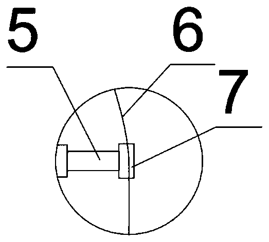
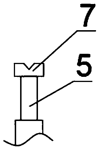
[0039]The present invention is a self-balancing lifting device and its control method, which includes a counterweight 1, a load box 2, and a rotating traction mechanism between the two. The rotating traction mechanism includes a rotating shaft 3 and a Traction mechanism, the traction mechanism includes a rotating disk 4, a telescopic device 5 and a traction rope 6 on the outside thereof; Above, the two ends of the traction rope 6 are respectively connected with the counterweight 1 and the load box 2; the top of the telescopic device is provided with a slot 7, and the traction rope 4 passes through the slot 7; the rotation The shaft 3 is connected to the electric motor or the hydraulic motor, the gravity sensor 8 is arranged at the connection between the traction rope 6 and the counterweight 1 and the load box 2, and the signal output end of the gravity sensor 8 is connected to the controller, and the The controller controls the telescopic length of the telescopic device 5; the...


PUM


Abstract

The invention belongs to the technical field of lifting equipment and relates to a self-balancing lifting device and a control method thereof. The self-balancing lifting device comprises a balancing weight, a load box body and a rotary traction mechanism arranged between the balancing weight and the load box body, wherein the rotary traction mechanism comprises a rotary shaft and a traction mechanism rotating along the rotary shaft, the traction mechanism comprises a rotary disc, telescopic devices and a traction rope, and the traction rope is arranged on the outer sides of the telescopic devices; the rotary disc is fixedly connected with the rotary shaft, the telescopic devices are circumferentially distributed on the rotary disc, and the two ends of the traction rope are connected with the balancing weight and the load box body correspondingly; clamping grooves are formed in the top ends of the telescopic devices, wherein the traction rope penetrates through the clamping grooves; andthe rotary shaft is connected with a motor or a hydraulic motor, gravity sensors are arranged at the joints between the traction rope and the balancing weight and the load box body, and the signal output ends of the gravity sensors are connected with a controller. According to the self-balancing lifting device and the control method thereof, the controller carries out real-time calculation, so that dynamic balance of the balancing weight and the load box body to the torque of the rotary shaft is achieved through controlling the extending length of each telescopic device, power requirements for the motor or the hydraulic motor are greatly reduced, and risks of major accidents caused by overload can be reduced.

Description

technical field [0001] The invention belongs to the technical field of lifting equipment, relates to a self-balancing lifting device, in particular to a self-balancing lifting device and a control method thereof. Background technique [0002] In lifting devices such as elevators, freight elevators, and linear pumping units, counterweights are used to balance the load, thereby reducing the power delivered by the electric or hydraulic motor. The counterweight force arm, load force arm and counterweight weight of the existing lifting device are often unchanged, the load that the counterweight can balance is limited, and the power demand for the electric motor or hydraulic motor is relatively high. In addition, when the equipment starts or brakes, the counterweight and load will be overweight or lose weight. At this time, the rotating shaft will bear a large starting or braking torque, and at the same time, it will impact the motor or hydraulic motor, making the rotating shaft ...

Claims


Application Information

Patent Timeline
IPC IPC(8): B66B17/12
CPCB66B17/12
Inventor 岳猛超张万武
Owner HEBEI KELI AUTOMOBILE EQUIP CO LTD
Learn More