
Vacuum centrifugal machine

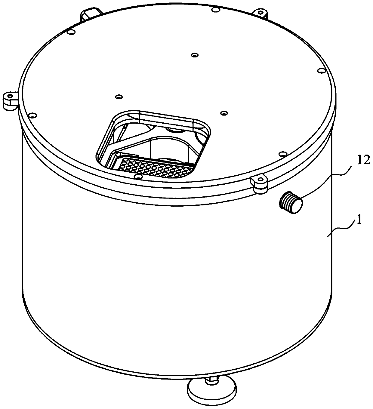
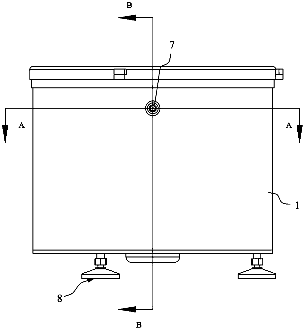
A centrifuge and vacuum technology, applied in the field of centrifuges, can solve the problems of complex structure and installation of the centrifuge rotor, and the cavity cannot dissipate heat and cool down, and achieve the effects of lowering temperature, preventing denaturation and high centrifugal efficiency

Pending Publication Date: 2020-05-22
广州高盛生物科技有限公司
View PDF0 Cites 2 Cited by
  • Summary
  • Abstract
  • Description
  • Claims
  • Application Information

AI Technical Summary

Problems solved by technology

[0003] The purpose of the present invention is to provide a vacuum centrifuge to solve the technical problems in the prior art that the rotor structure and installation of the centrifuge are complicated, and the cavity cannot dissipate heat and cool down. The structure is simplified, and the centrifugation efficiency is good. Sample properties are stable

Method used


Image

  • Vacuum centrifugal machine
  • Vacuum centrifugal machine
  • Vacuum centrifugal machine

Examples


Embodiment Construction

[0027] Embodiments of the present invention are described in detail below, and examples of the embodiments are shown in the drawings, wherein the same or similar reference numerals denote the same or similar elements or elements having the same or similar functions throughout. The embodiments described below by referring to the figures are exemplary and are intended to explain the present invention and should not be construed as limiting the present invention.

[0028] In the description of the present invention, unless otherwise clearly specified and limited, the terms "connected", "connected" and "fixed" should be understood in a broad sense, for example, it can be a fixed connection, a detachable connection, or an integrated ; It can be a mechanical connection or an electrical connection; it can be a direct connection or an indirect connection through an intermediary, and it can be the internal communication of two components or the interaction relationship between two compo...


PUM


Abstract

The invention discloses a vacuum centrifugal machine, and belongs to the technical field of centrifugal machines. The vacuum centrifugal machine comprises a centrifugal machine body, a rotor and a vacuum pump. A centrifugal cavity is formed in the centrifugal machine body. The rotor is arranged in the centrifugal cavity and provided with a plurality of containing grooves. Hanging baskets are clamped in the containing grooves and used for containing to-be-centrifuged samples and can centrifuge the multiple samples at the same time without mutual interference. The distances between the hanging baskets and the rotating axis of the rotor are the same, so that the centrifugal effect of all the samples is consistent, the centrifugal efficiency is high, and installing and using are convenient. The vacuum pump is connected with the centrifugal machine body and used for pumping and draining gas in the centrifugal cavity, so that the temperature in the centrifugal cavity is lowered, the degeneration of the samples is prevented, and the quality of the centrifuged samples is ensured. The vacuum centrifugal machine is high in efficiency, the quality of the samples is not affected before and after centrifuging, the centrifugal effect is good, and the internal structure and installation are simple.

Description

technical field [0001] The invention belongs to the technical field of centrifuges, in particular to a vacuum centrifuge. Background technique [0002] A centrifuge is a device that separates mixtures of different specific gravity by centrifugal force. Among them, the rotor is an important component, the sample to be centrifuged is fixed on the rotor, and the centrifugation of the sample is completed by the high-speed rotation of the rotor. At present, the structure of the rotor is a split type, which is composed of a rotor body, a hanger pin, a collar and other components. The hanger pin is installed on the rotor and fixed by the collar. The structure is complicated, and it takes time and effort to disassemble. In addition, when the above-mentioned centrifuge rubs against the air during high-speed rotation, a large amount of heat is generated, which causes the temperature in the centrifuge cavity to rise rapidly. Since different samples to be centrifuged have different sen...

Claims


Application Information

Patent Timeline
IPC IPC(8): B04B5/04B04B15/08
CPCB04B5/0421B04B15/08B04B2005/0435
Inventor 罗深恒陈光陈嘉棋
Owner 广州高盛生物科技有限公司
Learn More