Cable with herringbone members and photoelectric composite cable

A photoelectric composite cable and herringbone technology, applied in the field of electric power and cables, can solve problems such as troublesome production, decreased production efficiency, and increased product weight, and achieve the effect of fast stripping speed, fast production speed, and fewer components

Inactive Publication Date: 2020-05-19
常熟虞星光电科技有限公司
View PDF0 Cites 0 Cited by
  • Summary
  • Abstract
  • Description
  • Claims
  • Application Information

AI Technical Summary

Problems solved by technology

However, the cables in the prior art are not easy to peel and replace, and the use of wrapping components damages the protective layer and destroys the photoelectric performance, and the diversification of materials brings inconvenience to management, procurement, etc., and also reduces the weight of the product. aggravation, cost increase
On the other hand, due to the diversification of components in the cable, the production is troublesome, and complex and expensive cabling and stranding equipment is required, which greatly reduces the production efficiency. Uneconomical
The production of skeleton structures in the prior art requires complicated machines, which are basically monopolized by foreigners. How to use existing equipment to produce brackets / skeletons has become a technical problem that needs to be solved urgently in the industry

Method used


Image

  • Cable with herringbone members and photoelectric composite cable
  • Cable with herringbone members and photoelectric composite cable
  • Cable with herringbone members and photoelectric composite cable

Examples


Embodiment 1

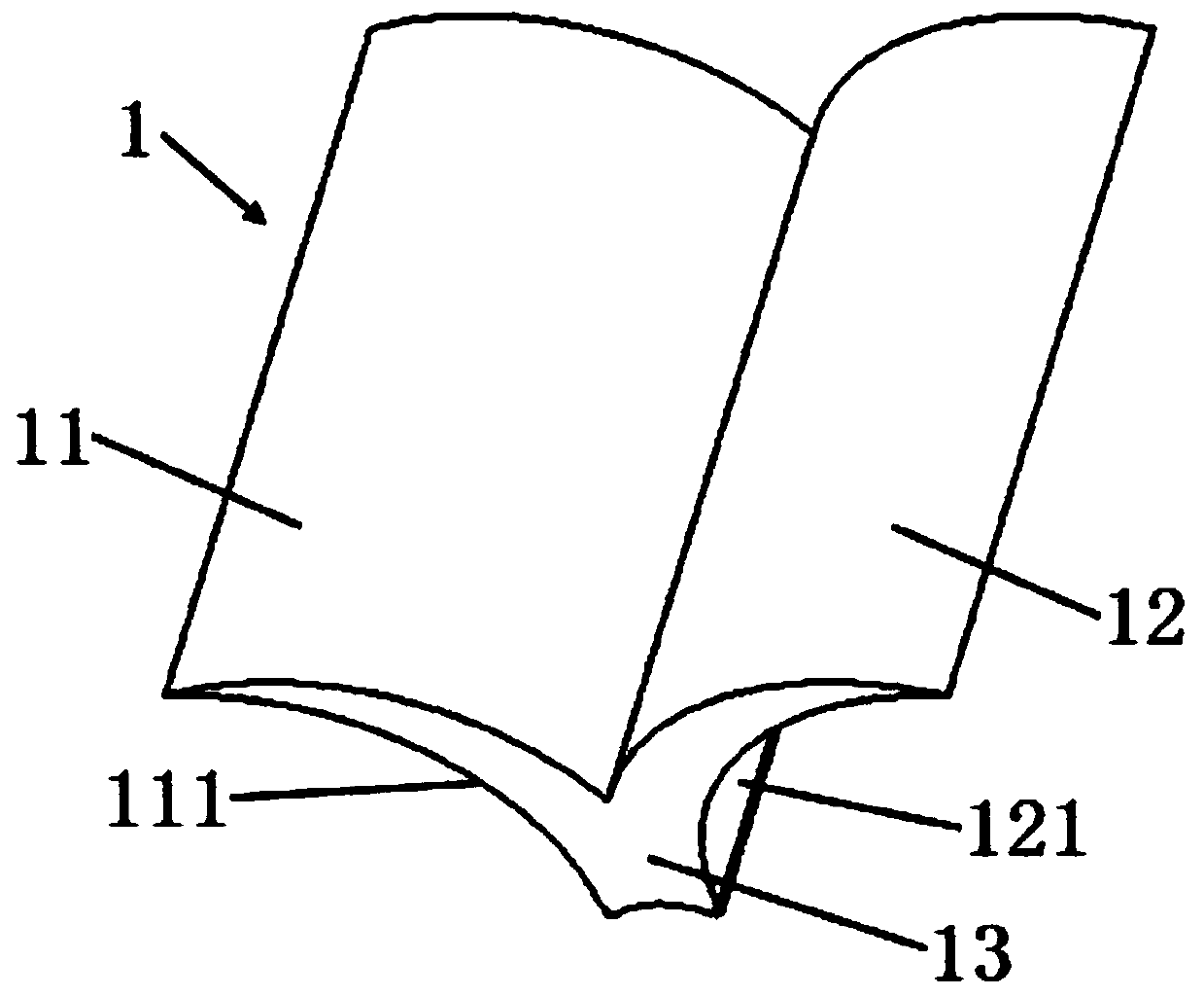
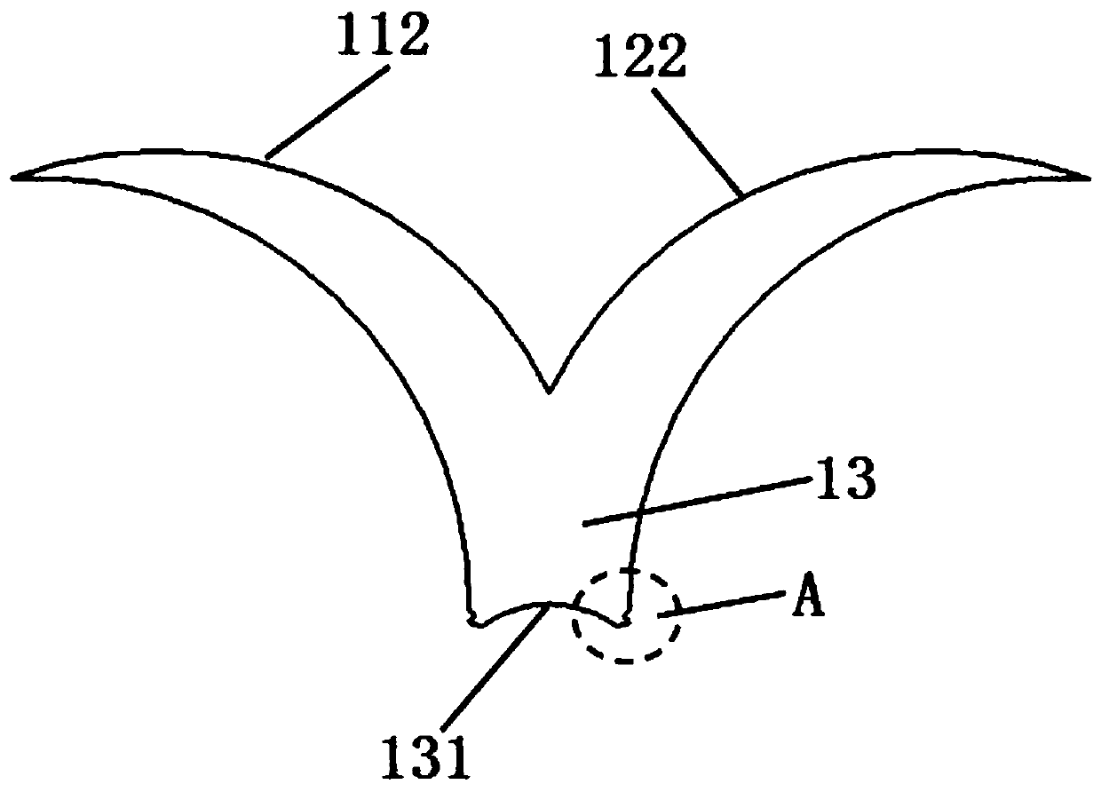
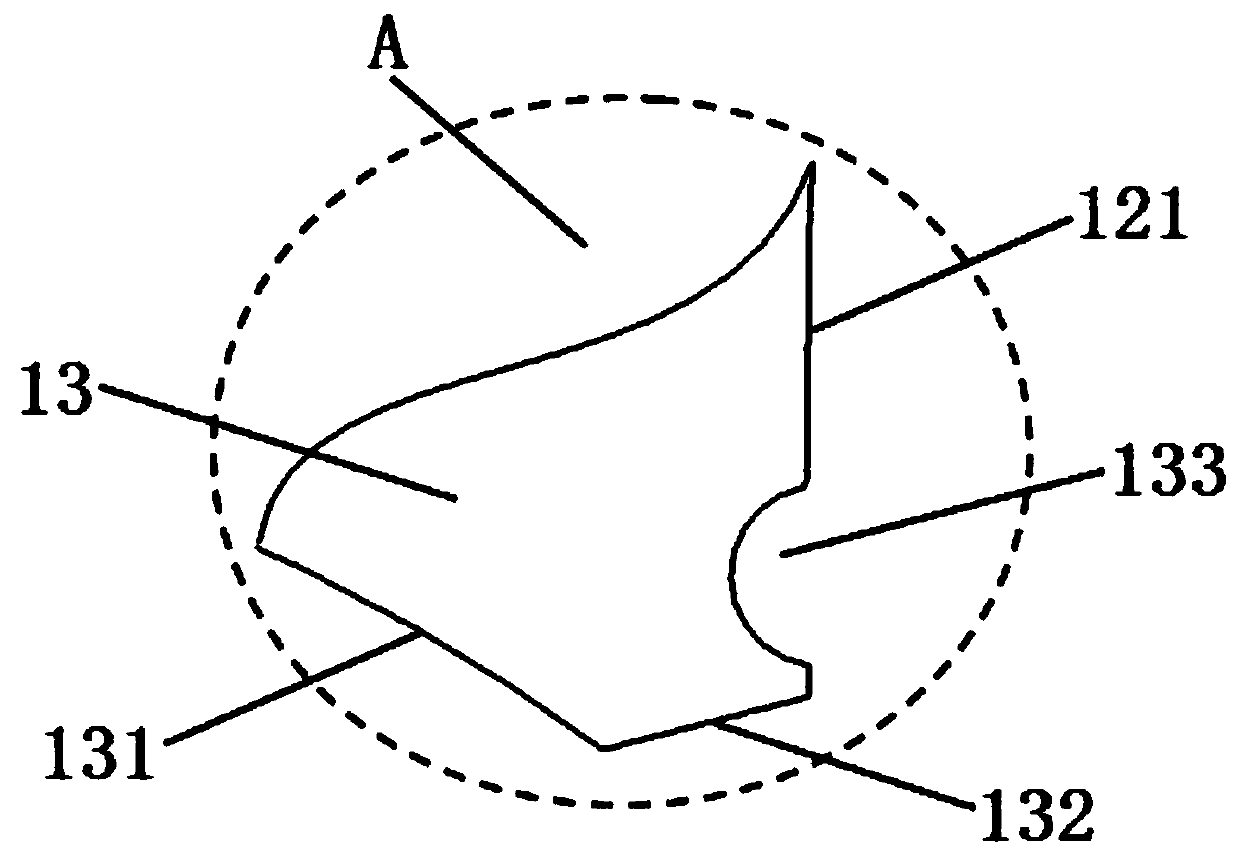
[0035] please see Figure 1 to Figure 8 , a photoelectric composite cable with a herringbone component, with a reinforcing member 2, a filling member 3, an electrical unit 4, an optical unit 5, and an outer sheath 7, and an optical fiber 6 inside the optical unit 5, characterized in that the optoelectronic There are also four chevron-shaped components 1 in the composite cable. The chevron-shaped components 1 are composed of a first bracket 11, a second bracket 12, and a third bracket 13. The first bracket 11 is curved at one end and gradually increases toward the other end. Knife shape, the first bracket inner wall 111 of the first bracket 11 is arc-shaped, the first bracket outer wall 112 of the first bracket 11 is arc-shaped, and the first bracket inner wall 111 and the first bracket outer wall 112 are all protrusions upward; The second bracket 12 is a curved knife shape that is pointed at one end and gradually increases toward the other end. The second bracket inner wall 12...

Embodiment 2

[0038] please see Figure 9 and Figure 10 , and refer to Figure 1 to Figure 8 , a cable with a herringbone member, which has a reinforcement 2, a filler 3, an electrical unit 4, and an outer sheath 7, and is characterized in that the cable also has four herringbone members 1, and the herringbone member 1 It consists of a first bracket 11, a second bracket 12, and a third bracket 13. The first bracket 11 is in the shape of a curved knife with a pointed end and gradually increases toward the other end. The inner wall 111 of the first bracket 11 is arc-shaped. The first bracket outer wall 112 of a bracket 11 is arc-shaped, and the first bracket inner wall 111 and the first bracket outer wall 112 are all convex upwards; the second bracket 12 is in the shape of a curved knife with a pointed end and gradually increasing toward the other end , the second bracket inner wall 121 of the second bracket 12 is arc-shaped, the second bracket outer wall 122 of the second bracket 12 is ar...

Embodiment 3

[0040] please see Figure 11 and Figure 12 , and refer to Figure 1 to Figure 10 , a photoelectric composite cable with a herringbone component, has a reinforcing member 2, a filling member 3, an electrical unit 4, an optical unit 5, and an outer sheath 7, and the optical unit 5 has an optical fiber 6, which is characterized in that the optoelectronic There are also four chevron-shaped components 1 in the composite cable. The chevron-shaped components 1 are composed of a first bracket 11, a second bracket 12, and a third bracket 13. The first bracket 11 is curved at one end and gradually increases toward the other end. Knife shape, the first bracket inner wall 111 of the first bracket 11 is arc-shaped, the first bracket outer wall 112 of the first bracket 11 is arc-shaped, and the first bracket inner wall 111 and the first bracket outer wall 112 are all protrusions upward; The second bracket 12 is a curved knife shape that is pointed at one end and gradually increases towar...


PUM


Abstract

The invention belongs to the field of cables, and relates to a cable with herringbone members. The cable is provided with a reinforcing piece, filling pieces, an electric unit and an outer sheath, andis characterized by further comprising herringbone members, wherein the herringbone members are spliced to form a cylinder shape, a support cavity is formed between the inner wall of a first supportand the inner wall of a second support of the adjacent herringbone members, and the electric unit is placed in the support cavity; the first side edge and the second side edge of the filling piece areattached to the outer wall of the first support and the outer wall of the second support of the herringbone member, the first side edges of the filling pieces of all the filling pieces are located onthe same cylindrical surface, and the herringbone members and the filling pieces are wrapped with the outer sheath. The invention also discloses a photoelectric composite cable. The cable has the following main beneficial effects of fewer members, easier management, lower cost, higher production speed, higher stripping speed, replaceable electric unit and lighter product weight, and internal members or parts are prevented from being pricked by binding materials.

Description

technical field [0001] The invention belongs to the technical field of electric power and cables, and in particular relates to a cable with a herringbone member and a photoelectric composite cable. Background technique [0002] As a pillar industry in the national economy, cables are increasingly used. However, the cables in the prior art are not easy to peel and replace, and the use of wrapping components damages the protective layer and destroys the photoelectric performance, and the diversification of materials brings inconvenience to management, procurement, etc., and also reduces the weight of the product. Aggravation, cost increase. On the other hand, due to the diversification of components in the cable, the production is troublesome, and complex and expensive cabling and stranding equipment is required, which greatly reduces the production efficiency. Uneconomical. The production of skeleton structures in the prior art requires complex machines, and such equipment...

Claims


Application Information

Patent Timeline
Patent Type & Authority Applications(China)
IPC IPC(8): H01B7/17H01B7/18H01B7/22H01B7/38H01B9/00H01B11/22G02B6/44
CPCG02B6/4432H01B7/17H01B7/18H01B7/22H01B7/38H01B9/005H01B11/22
Inventor 沈群华
Owner 常熟虞星光电科技有限公司
Why Eureka
Try Eureka