Layering type drying device for grain
A drying device and layered technology, applied in the field of grain layered drying devices, can solve the problems of insufficient drying of grains, poor drying effect, etc., and achieve simple structure, easy popularization and application, and improved drying. The effect of drying efficiency
- Summary
- Abstract
- Description
- Claims
- Application Information
AI Technical Summary
Problems solved by technology
Method used
Image
Examples
Embodiment 1
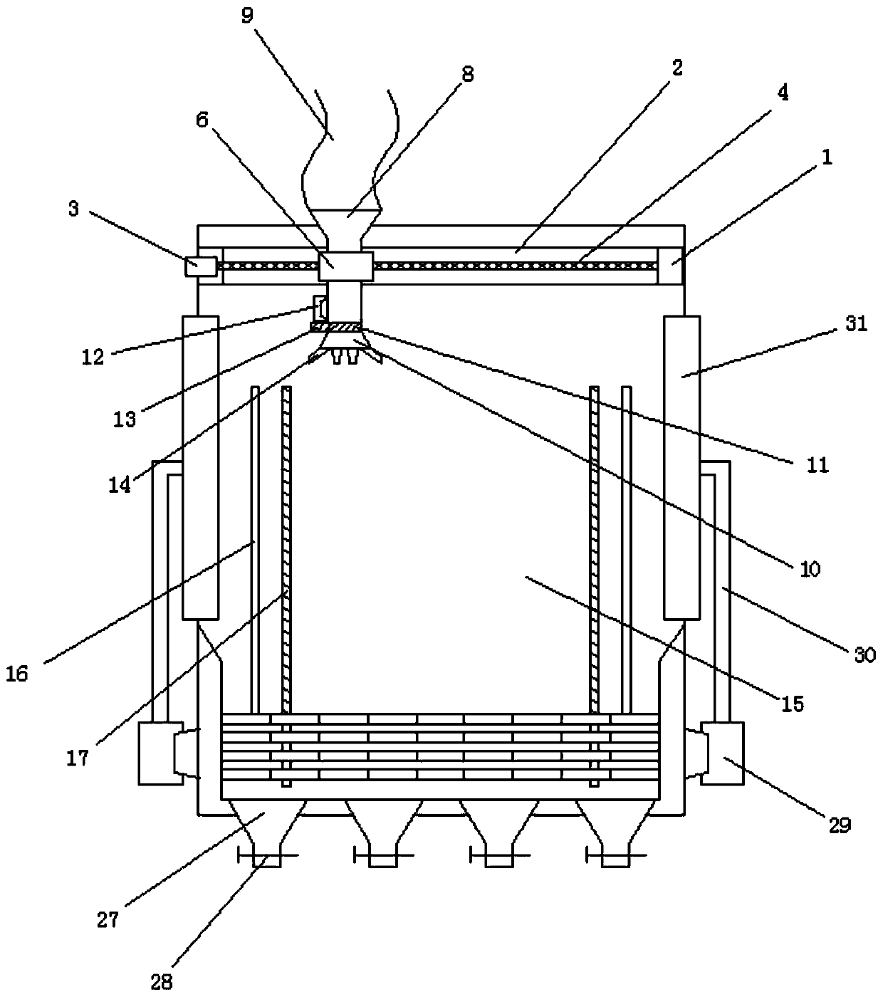
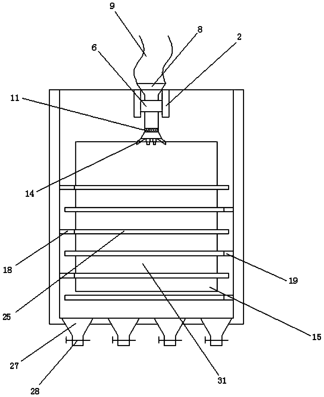
[0030] Embodiment 1: as Figure 1-7 As shown, a grain layered drying device includes a drying bin 15, the top of the drying bin 15 is fixedly equipped with a blanking rack 1, and the middle part of the blanking rack 1 is provided with a limiting groove 2, so that The left end of the blanking rack 1 is fixedly connected with a first motor 3, and the right end of the first motor 3 is fixedly connected with a reciprocating screw 4, and the right end of the reciprocating screw 4 is rotatably connected with the right side wall of the limiting groove 2 ;
[0031] A moving block 6 is movably connected in the limiting groove 2, and the reciprocating screw rod 4 is connected with the moving block 6 by a screw thread. The top of the moving block 6 is penetrated with a through groove 7, and the through groove 7 A feed hopper 8 is fixed inside; the moving block can be movably clamped in the limit slot, and the reciprocating screw rod is driven by the first motor to rotate, driving the mo...
Embodiment 2
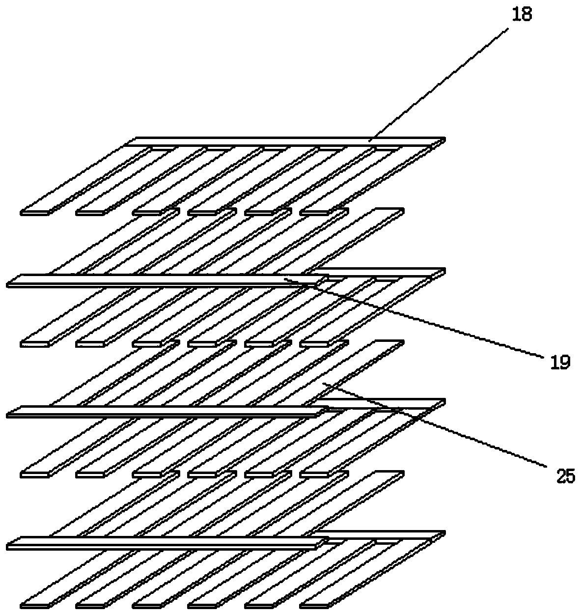
[0042] Embodiment 2: as Figure 1-8 As shown, a grain layered drying device includes a drying bin 15, the top of the drying bin 15 is fixedly equipped with a blanking rack 1, and the middle part of the blanking rack 1 is provided with a limiting groove 2, so that The left end of the blanking rack 1 is fixedly connected with a first motor 3, and the right end of the first motor 3 is fixedly connected with a reciprocating screw 4, and the right end of the reciprocating screw 4 is rotatably connected with the right side wall of the limiting groove 2 ;
[0043] A moving block 6 is movably connected in the limiting groove 2, and the reciprocating screw rod 4 is connected with the moving block 6 by a screw thread. The top of the moving block 6 is penetrated with a through groove 7, and the through groove 7 A feed hopper 8 is fixed inside; the moving block can be movably clamped in the limit slot, and the reciprocating screw rod is driven by the first motor to rotate, driving the movi...
PUM
 Abstract
Description
Claims
Application Information
 - R&D
- Intellectual Property
- Life Sciences
- Materials
- Tech Scout
- Unparalleled Data Quality
- Higher Quality Content
- 60% Fewer Hallucinations
Browse by: Latest US Patents, China's latest patents, Technical Efficacy Thesaurus, Application Domain, Technology Topic, Popular Technical Reports.
© 2025 PatSnap. All rights reserved.Legal|Privacy policy|Modern Slavery Act Transparency Statement|Sitemap|About US| Contact US: help@patsnap.com


