
An automatic charging pile, a charging control system and a charging method

An automatic charging and charging control technology, which is applied to electric vehicle charging technology, charging stations, electric vehicles, etc., can solve problems such as low charging efficiency, damage to the charging gun, and user burden, and achieve improved charging efficiency, increased charging power, and The effect of improving work efficiency

Active Publication Date: 2021-04-09
ZHENGZHOU AFFIRMATIVE TECH LTD
View PDF7 Cites 0 Cited by
  • Summary
  • Abstract
  • Description
  • Claims
  • Application Information

AI Technical Summary

Problems solved by technology

After parking, the user needs to manually unplug the charging gun and plug it into the charging port of the electric vehicle for charging. The operation is complicated and burdens the user, especially for the field of shared cars.
In addition, the charging efficiency of this charging method is not high. If the charging power is increased, the charging gun and charging cable will inevitably become thicker and heavier, which will affect the convenience of operation.
Manual operation of the charging gun may also cause damage to the charging gun due to improper use
[0003] Not only electric vehicles have charging problems, but some engineering vehicles and other vehicles, such as electric forklifts, also have charging problems. Charging efficiency will directly affect work efficiency

Method used


Image

  • An automatic charging pile, a charging control system and a charging method
  • An automatic charging pile, a charging control system and a charging method
  • An automatic charging pile, a charging control system and a charging method

Examples


Embodiment 1

[0060]The charging pile in this embodiment is the same as the charging pile in the above-described charging control system embodiment, and the difference is that the specific configuration and principles of the automatic charging pile will not be described again.

Embodiment 2

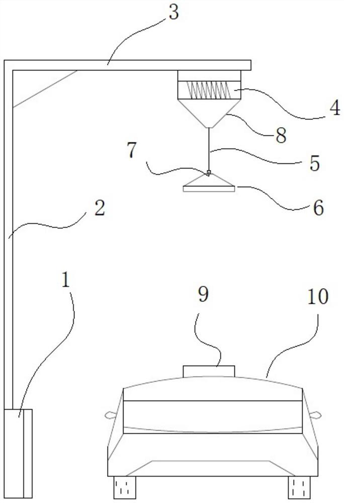
[0062]Compared with Example 1, the charging pile of Example 1 applies to indoor parking spaces such as underground garages, and also suitable for outdoor parking spaces. For some underground parking spaces or indoor parking spaces, the charging pile can also be designed, no longer set up a column, but set the charging pile to hang the top of the wall, reduce the space occupied by the ground, such asFigure 6 Indicated.


PUM


Abstract

The invention relates to an automatic charging pile, a charging control system and a charging method. The automatic charging pile includes a charging machine, the charging machine is connected with a cable, the end of the cable is provided with a charging head, the charging head is suspended in the air, and the charging head is connected with the charging head. The cable on one side is wound on the winding wheel, and the winding wheel controls the lifting of the charging head; there is a light source in the charging head, which can emit light beams downward, and is used to cooperate with the charging stand on the vehicle to be charged to realize vehicle positioning; There is a charging part and an electromagnet on the lower side of the charging head. The charging part is conductively matched with the receiving part on the charging stand. The electromagnet is used to attract the positioning part on the charging stand to ensure the docking of the charging part and the receiving part; charging The head is also provided with a communication interface for communicating with the battery in the vehicle to be charged. The charging process does not require manual operation, and is highly automated and very convenient. It also provides conditions for setting the power distribution box to high power, thereby improving the charging efficiency of electric vehicles.

Description

Technical field[0001]The present invention relates to the field of automatic charging technology, and more particularly to an automatic charging pile, a charging control system, and a charging method.Background technique[0002]As a new energy vehicle, electric vehicle is widely optimistic because of its traditional fuel cars. Electric vehicles are generally powered by lithium-ion batteries. As electric vehicles have more and more, charging has also become a problem. At present, there is a relatively large type of charging pile, which includes a charging gun and a distribution box set next to the parking space. After the user is parked, it needs to manually pull the charging gun, and the charging interface inserted into the electric vehicle is charged, and the operation is complex, and the user has caused a burden, especially for the shared car. In addition, this charging method is not high, if the charging power is increased, the charging gun and the charging line are bound to become...

Claims


Application Information

Patent Timeline
Patent Type & Authority Patents(China)
IPC IPC(8): B60L53/35B60L53/37B60L53/36B60L53/16B60L53/18B60L53/30
CPCB60L53/16B60L53/18B60L53/30B60L53/35B60L53/36B60L53/37Y02T10/70Y02T10/7072Y02T90/12Y02T90/14Y02T90/16
Inventor 王科锋
Owner ZHENGZHOU AFFIRMATIVE TECH LTD
Learn More