
Boiler economizer pipeline manufacturing, machining and forming method

An economizer pipe, processing and forming technology, applied in the direction of manufacturing tools, chemical instruments and methods, metal processing equipment, etc., can solve the problems of pipeline impurities, affecting the welding effect, long storage time of pipelines, etc., and achieve the goal of ensuring continuity Effect

Active Publication Date: 2020-05-19
旋力热能(湖北)有限公司
View PDF7 Cites 0 Cited by
  • Summary
  • Abstract
  • Description
  • Claims
  • Application Information

AI Technical Summary

Problems solved by technology

[0003] However, the manufacturing, processing and forming methods of boiler economizer pipelines in the market currently have the following problems in the operation process: a. The traditional manufacturing process cannot quickly complete the positioning of the fins when welding the pipes and fins, that is, different effective At the same time, once the fins are subjected to external force during the welding process, the fins will shake to a certain extent, which will affect the welding effect; b. Due to the long storage time of the pipeline, or Affected by environmental factors, some impurities will appear on the surface wall of the pipeline, which will cause virtual welding to occur during the welding process.

Method used


Image

  • Boiler economizer pipeline manufacturing, machining and forming method
  • Boiler economizer pipeline manufacturing, machining and forming method
  • Boiler economizer pipeline manufacturing, machining and forming method

Examples


Embodiment Construction

[0033] In order to make the technical problems, technical solutions and beneficial effects to be solved by the present invention clearer, the present invention will be further described in detail below in conjunction with the accompanying drawings and embodiments. It should be understood that the specific embodiments described here are only used to explain the present invention, not to limit the present invention.

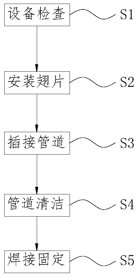
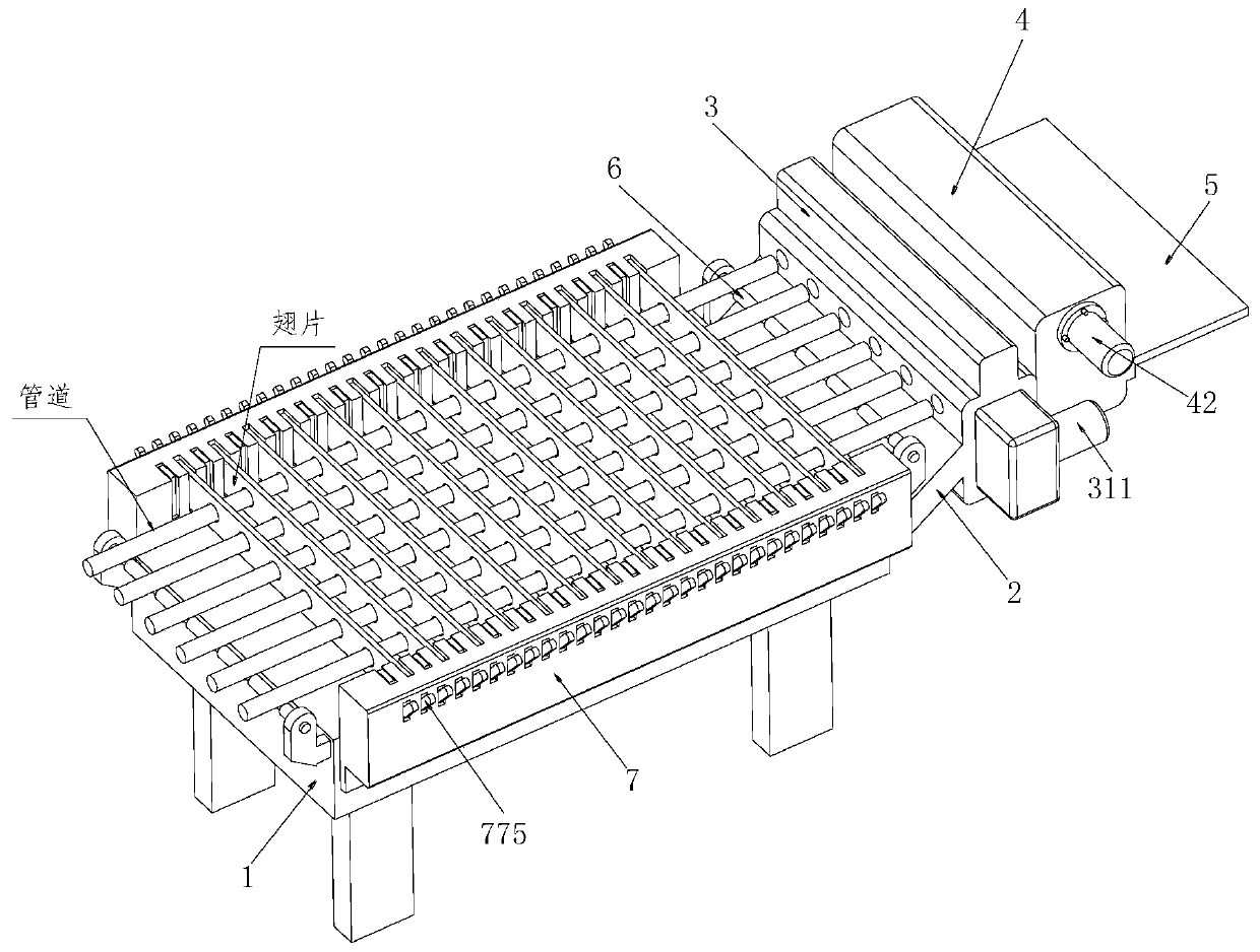
[0034] Refer to 1-9, a boiler economizer pipeline manufacturing processing molding method, which uses a boiler economizer pipeline manufacturing processing molding device, the boiler economizer pipeline manufacturing processing molding device includes a support table 1. The supporting plate 2, the cleaning mechanism 3, the conveying mechanism 4, the placing plate 5, the support roller 6 and the positioning and fixing mechanism 7, when using the above-mentioned boiler economizer pipeline manufacturing processing forming device to weld the pipe and fin Methods as bel...


PUM


Abstract

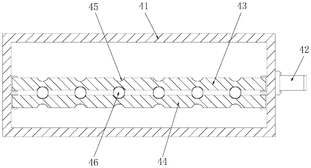
The invention relates to a boiler economizer pipeline manufacturing, machining and forming method. The boiler economizer pipeline manufacturing, machining and forming method comprises a supporting table top, a bearing plate, a cleaning mechanism, a conveying mechanism, a placing plate, supporting rollers and positioning and fixing mechanisms, wherein the bearing plate is welded to one end of the supporting table top, the cleaning mechanism is installed at one end of the bearing plate, the side wall of the cleaning mechanism is connected with the conveying mechanism, the placing plate is installed on one side of the conveying mechanism, positioning and fixing mechanisms are installed on the two sides of the supporting table top, the supporting rollers are installed at the two ends of the supporting table top through fixing frames, a metal shell A is welded to one end of the bearing plate, a driving unit is arranged at one end of the metal shell A, a bearing rod is movably installed inside the metal shell A, and bearings are embedded in the interior of the bearing rod at equal intervals. According to the boiler economizer pipeline manufacturing, machining and forming method, rapid installing of fins can be achieved, an installing device is high in stability, the fins cannot shake, meanwhile, the outer wall of a pipeline can be cleaned in the inserting process of the pipeline, andnormal execution of the welding process is guaranteed.

Description

technical field [0001] The invention relates to the technical field of production of economizer pipelines, in particular to a method for manufacturing, processing and forming boiler economizer pipelines. Background technique [0002] The economizer is a device installed at the lower part of the boiler tail flue to recover the waste heat of the exhausted smoke. It heats the boiler feed water into a saturated water heating surface under the pressure of the steam drum. Because it absorbs the heat of the high-temperature flue gas, it reduces It improves the exhaust temperature of the flue gas, saves energy and improves efficiency, so it is called an economizer. Pipeline economizers are not limited by pressure and are generally made of carbon pipes with an outer diameter of 32 to 51 mm. Sometimes fins and ribs are added to the tube to improve heat transfer. [0003] However, the manufacturing, processing and forming methods of boiler economizer pipelines in the market currently...

Claims


Application Information

Patent Timeline
Patent Type & Authority Applications(China)
IPC IPC(8): B23K37/04B08B9/023
CPCB08B9/023B08B2209/02B23K37/04B23K37/0443
Inventor 王德忠汪尹
Owner 旋力热能(湖北)有限公司
Learn More