High-voltage equipment box

A technology for high-voltage equipment boxes and high-voltage areas, which is applied to the setting of switchgear, supporting insulators, grounding devices, etc., can solve the problems of unfavorable vehicle roof installation structure load-bearing, inconvenient maintenance, and the overall volume and weight of the box. Improve the safety of maintenance, reduce the weight of the box, and ensure the effect of insulation isolation

Active Publication Date: 2020-05-15
ZHUZHOU ELECTRIC LOCOMOTIVE CO
View PDF13 Cites 4 Cited by
  • Summary
  • Abstract
  • Description
  • Claims
  • Application Information

AI Technical Summary

Problems solved by technology

Therefore, when the high-voltage switch products have faults in the action mechanism, low-voltage line, or pneumatic components, the sealed top cover of the high-voltage equipment box must be opened on the roof, and then the equipment must be removed from the box before maintenance. convenient
In addition, the different high-voltage equipment in the existing high-voltage equipment box are side-mounted on the side wall of the box, and the insulation performance is guaranteed through the bottom insulating partition. In this type of installation structure, the volume of the box is occupied by the space of the side wall by the independent high-voltage equipment The decision resulted in part of the existing high-voltage equipment box being idle, and the overall volume and weight of the box were relatively large, which was not conducive to the load-bearing of the roof installation structure.

Method used


Image

  • High-voltage equipment box
  • High-voltage equipment box
  • High-voltage equipment box

Examples


Embodiment Construction

[0035] The present invention will be further described below in conjunction with the embodiments and accompanying drawings.

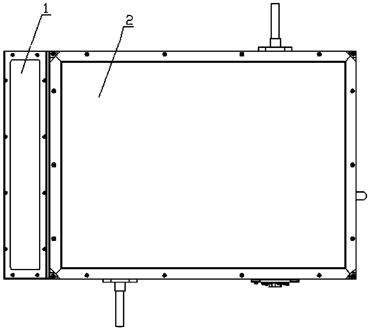
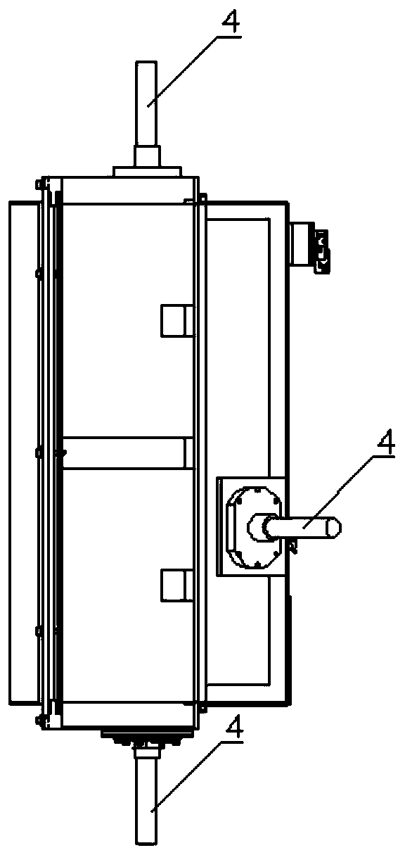
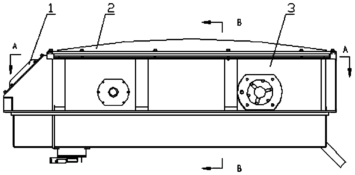
[0036] Such as Figure 1-16 As shown, a high-voltage equipment box includes a box body 3. The box body 3 is the mechanical installation body for carrying the equipment in the box body. 4. The inside of the box body 3 is divided into two parts, the high-pressure area and the low-pressure area, by an aluminum alloy partition plate 3.1. The main top cover 2, the inspection cover 1 and the main top cover 2 are installed on the box body through fasteners. During maintenance, only the inspection cover 1 needs to be disassembled, and the main top cover 2 is in a sealed and closed state for a long time.

[0037] The specific structure in the box body 3 includes: high-voltage grounding switch 5, voltage transformer 6, bottom insulation partition 7, middle insulation partition 8, voltage equalizing ring 9, lightning arrester 10, high-voltage isolation switch 11...


PUM


Abstract

A high-voltage device box comprises a box body, and a high-voltage grounding switch, a voltage transformer, a lightning arrester, a high-voltage isolation switch and a vacuum circuit breaker which arelocated in the box body. The interior of the box body is divided into a low-voltage area and a high-voltage area through a partition plate, the low-voltage part of the high-voltage isolation switch and the low-voltage part of the vacuum circuit breaker are both installed in the low-voltage area, and the high-voltage grounding switch and the high-voltage part of the vacuum circuit breaker are bothinstalled at the side, located in the high-voltage area, of the partition plate. The high-voltage part of the high-voltage isolation switch is installed on the bottom face of the high-voltage area through a supporting insulator, and the voltage transformer and the lightning arrester are installed on the two opposite side walls of the high-voltage area respectively. An overhaul cover plate is arranged at the upper portion of the low-voltage area, and a main top cover is arranged at the upper portion of the high-voltage area. According to the high-voltage device box, the maintenance of the high-voltage device is facilitated after the high-voltage and low-voltage partitioning, and the high-voltage device adopts a mode of combining the side wall installation and the bottom surface installation, so that the overall size of the high-voltage device box can be reduced.

Description

technical field [0001] The invention belongs to equipment for electric locomotives and train sets, in particular to a high-voltage equipment box. Background technique [0002] High-voltage equipment box for electric locomotives and EMUs, the main high-voltage equipment in the box is: vacuum circuit breaker, high-voltage grounding switch, high-voltage isolating switch, voltage transformer and lightning arrester, etc. Among them, the high-voltage isolating switch is equipped with low-voltage components (pneumatic components and Dc110V Low-voltage circuit components), vacuum circuit breakers also include low-voltage control parts (drive mechanism, pneumatic components and DC110V low-voltage circuit components). [0003] At present, electric locomotives and EMUs use high-voltage equipment boxes to uniformly install the above-mentioned equipment in one box. The equipment layout is based on the convenience of high-voltage cable entry and exit, and the maintenance of high-voltage s...

Claims


Application Information

Patent Timeline
Patent Type & Authority Applications(China)
IPC IPC(8): H02B1/46H02B1/48H02B1/16H02B13/035H01B17/16H01B17/38
CPCH02B1/46H02B1/48H02B1/16H02B13/0354H01B17/16H01B17/38H02B13/02B60L3/0069B60L2200/26
Inventor 李涛蒋聪健罗传文恒放王雄波彭鑫
Owner ZHUZHOU ELECTRIC LOCOMOTIVE CO
Why Eureka
Try Eureka