Pneumatic hydraulic corrugated pipe annular combination type wear-resisting ball valve

A pneumatic hydraulic, bellows technology, applied in valve details, valve devices, engine components, etc., can solve problems such as frequent operating failures, excessive leakage, and strain.

Pending Publication Date: 2020-05-15
白龙山
View PDF0 Cites 5 Cited by
  • Summary
  • Abstract
  • Description
  • Claims
  • Application Information

AI Technical Summary

Problems solved by technology

In the past 10 years of use, the life of imported valves has not reached the actual life of 20,000 online operations, especially the lock bucket valve, slag lock valve, and silicon powder valve, which have frequent operational failures and seriously affect the entire device. normal production
When these valves are used for one year, some even a few months, there will be problems: First, the opening and closing torque of the valve is too large, the ball switch is not in place, the valve seat bites the spherical surface, and the ball is severely chipped, which is easy to cause the ball Stuck
Second, even if it is not stuck, the valve seat and the spherical surface are severely worn and strained, which makes the sealing surface invalid and the leakage seriously exceeds the standard.
Of course, it is known that this kind of parking will cause great economic losses to the company. In order to avoid accidental parking, several domestic valve factories have carried out localization innovation on imported valves.

Method used


Image

  • Pneumatic hydraulic corrugated pipe annular combination type wear-resisting ball valve
  • Pneumatic hydraulic corrugated pipe annular combination type wear-resisting ball valve
  • Pneumatic hydraulic corrugated pipe annular combination type wear-resisting ball valve

Examples


Embodiment Construction

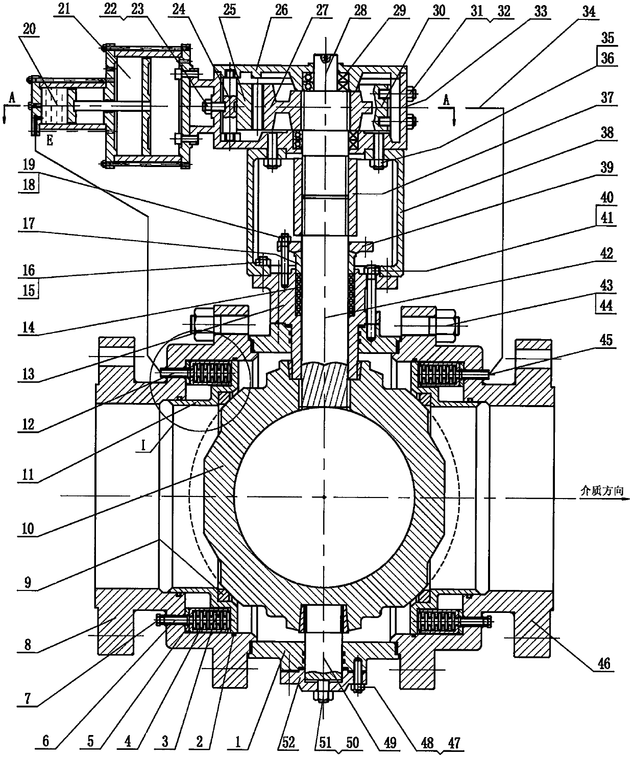
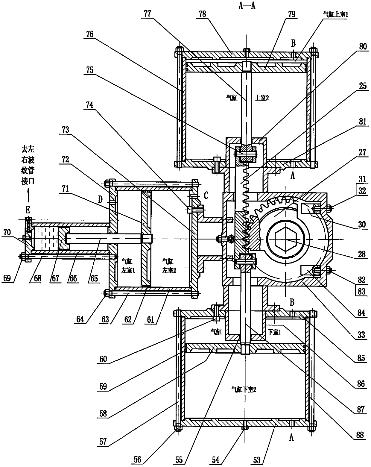
[0017] The working principles of the embodiments of the present invention will be described below in conjunction with the accompanying drawings.

[0018] 1. When the valve is closed:

[0019] The power-off signal sent from the control room de-energizes the solenoid valve F1, the solenoid valve F1 switches to the air port 4 with air pressure output, and the air control valve F2 acts, and then the air port 4 has air pressure output, the air pressure is divided into two ways: one way Supply air to the A port of the upper and lower cylinders, and the other to supply air to the air port 1 of the shaft control valve F3 (the valve is temporarily inactive and has no air pressure output). At this time, the air pressure supplied by the A port of the cylinder enters the upper chamber 2 and the lower chamber 2 of the cylinder. Then the upper and lower pistons 79, 58 are pressed and pushed upwards, and the upper and lower piston rods 77, 84 also move upwards together, and the push-pull rac...


PUM


Abstract

The invention discloses a pneumatic hydraulic corrugated pipe annular combination type wear-resisting ball valve, and belongs to inventions and creations in the aspect of special ball valves. The novel valve is developed to solve the prominent problems that a lock hopper valve and a lock slag valve used in an existing coal chemical industry device and a silicon powder valve of a polycrystalline silicon device are unstable in operation, short in service life and the like. According to the pneumatic hydraulic corrugated pipe annular combination type wear-resisting ball valve, each of an inner cavity of a left valve body and an inner cavity of a right valve body is provided with an annular multi-corrugated-pipe combined hydraulic pusher and a hydraulic sealing valve seat, each valve seat is designed to be a movable contact spherical surface and controls sealing through hydraulic pressure, in the rotation process of a ball body, friction is not generated between valve seat sealing rings and the spherical surfaces, only when the valve is closed, the sealing rings and the spherical surfaces are closed to form reliable sealing, and therefore, the service life of the valve is reliably guaranteed, and the valve opening and closing torque is small, so that operation is time-saving and labor-saving.

Description

technical field [0001] The "pneumatic hydraulic bellows ring group wear-resistant ball valve" of the present invention belongs to the invention and creation of special ball valves. The invention relates to special valves for process pipelines in petrochemical, power plant, metallurgy, coal chemical and other industries. Background technique [0002] The main task of the present invention is aimed at the existing coal chemical plant and polysilicon chemical plant, as well as the steel plant slurry working condition device, etc., the imported special valves and the special valves that are being localized can no longer meet the above working conditions in use. Requirements, the process conditions of the device are complicated, the working conditions are very harsh, and the technical requirements for the equipment are strict, so the key equipment in the device are all imported products. In the past 10 years of use, the life of imported valves has not reached the actual life of ...

Claims


Application Information

Patent Timeline
IPC IPC(8): F16K5/06F16K5/08F16K5/20F16K25/00F16K31/06F16K31/122F16K31/54
CPCF16K5/0605F16K5/0647F16K5/0689F16K5/0694F16K5/207F16K25/00F16K31/0644F16K31/122F16K31/1225F16K31/535F16K31/54
Inventor 白龙山
Owner 白龙山
Why Eureka
Try Eureka