
Assembled electrical prefabrication conduit construction method

A technology of electrical prefabrication and construction methods, which is applied in the direction of electrical components, cable installation, cable installation devices, etc., can solve the problems of wasted processing time, uneven processing quality, and the next process cannot be carried out normally, so as to improve the service life , to solve the effect of long processing time

Inactive Publication Date: 2020-05-15
SHANGHAI BAOYE GRP CORP
View PDF4 Cites 0 Cited by
  • Summary
  • Abstract
  • Description
  • Claims
  • Application Information

AI Technical Summary

Problems solved by technology

[0002] With the continuous development of society, a large number of standard floors are designed for engineering construction projects. In order to increase the pouring speed, the main floor adopts advanced aluminum molds, prefabricated PC components, self-elevating scaffolding technology and other technologies. The goal is to pour a floor in 3 days. This process Including steel bar binding of structural beams and slabs, installation of aluminum formwork, pre-embedding of electromechanical pipelines, concrete pouring and other professional interspersed operations. However, in the actual construction process, traditional electrical conduit pre-buried is usually bent and cut at the working level , Deburring, assembly and connection and other processes, due to the many construction processes and many cross operations, often the next process cannot be carried out normally because a certain process is not completed or the quality has not passed the acceptance, and finally the concrete cannot be poured and tamped on time. Nodes cannot be completed, a lot of processing time is wasted, a lot of scrap is generated, and the processing quality is uneven

Method used


Image

  • Assembled electrical prefabrication conduit construction method
  • Assembled electrical prefabrication conduit construction method

Examples


Embodiment Construction

[0025] The following will clearly and completely describe the technical solutions in the embodiments of the present invention with reference to the accompanying drawings in the embodiments of the present invention. Obviously, the described embodiments are only some, not all, embodiments of the present invention. Based on the embodiments of the present invention, all other embodiments obtained by persons of ordinary skill in the art without making creative efforts belong to the protection scope of the present invention.

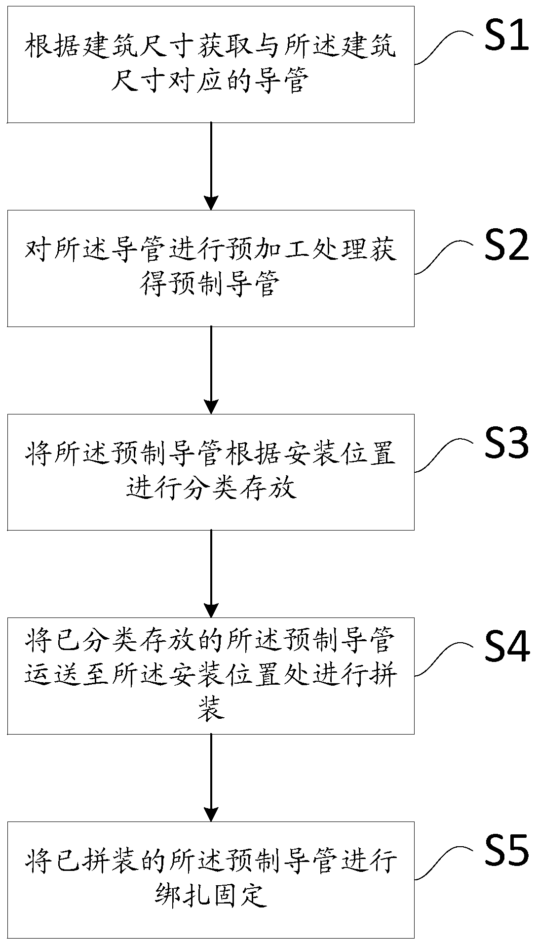
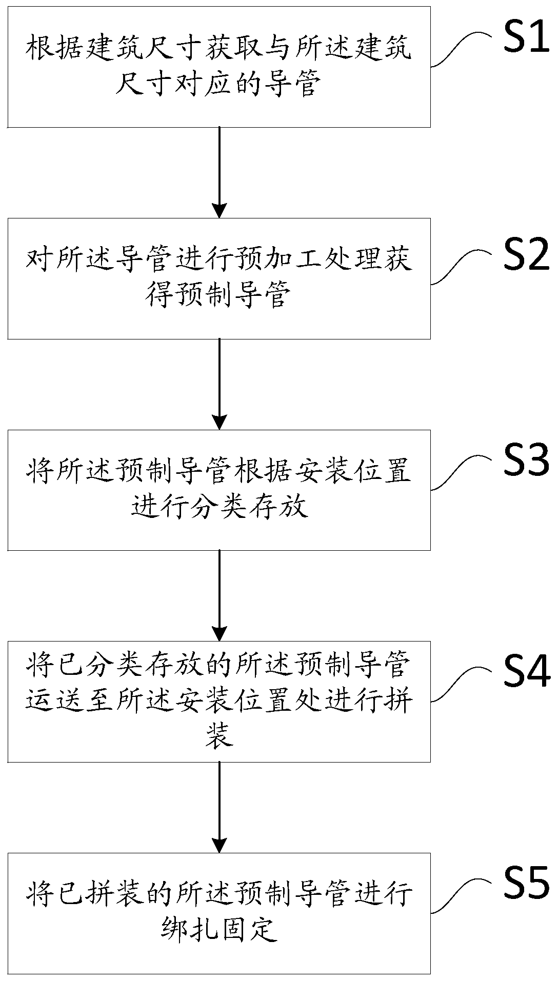
[0026] Please refer to figure 1 , figure 1 It is a schematic diagram of the overall structure of a specific embodiment provided by the present invention.

[0027] Such as figure 1 as shown, figure 1 A flow chart of the construction method of an assembled electrical prefabricated conduit provided for this scheme, according to figure 1 Describe this program in detail.

[0028] In a specific embodiment provided by the present invention, the construction meth...


PUM


Abstract

The invention discloses an assembled electrical prefabrication conduit construction method. The assembled electrical prefabrication conduit construction method comprises the steps that conduits corresponding to a building size are obtained according to the building size; pre-machining treatment is conducted on the conduits to obtain prefabrication conduits; the prefabrication conduits are stored in a classified mode according to mounting positions; the prefabrication conduits stored in the classified mode are conveyed to the mounting positions for assembly; and the assembled prefabrication conduits are fixed in a bound mode. According to the provided assembled electrical prefabrication conduit construction method, before the electrical conduits are pre-buried, the conduits are subjected toprocedures such as in-advance bending, cutting, deburring, and assembly connection, the problems of long machining time on an operation layer, congestion of multi-work machining spaces, low machiningquality pass rate and the like in the site construction process are solved, meanwhile, after being fixed in the bound mode, the conduits are further inspected and protected, and the service life of the conduits is prolonged.

Description

technical field [0001] The invention relates to the technical field of building construction, in particular to a construction method for an assembled electrical prefabricated conduit. Background technique [0002] With the continuous development of society, a large number of standard floors are designed for engineering construction projects. In order to increase the pouring speed, the main floor adopts advanced aluminum molds, prefabricated PC components, self-elevating scaffolding technology and other technologies. The goal is to pour a floor in 3 days. This process Including steel bar binding of structural beams and slabs, installation of aluminum formwork, pre-embedding of electromechanical pipelines, concrete pouring and other professional interspersed operations. However, in the actual construction process, traditional electrical conduit pre-buried is usually bent and cut at the working level , Deburring, assembly and connection and other processes, due to the many cons...

Claims


Application Information

Patent Timeline
Patent Type & Authority Applications(China)
IPC IPC(8): B23P15/00H02G1/00H02G3/00H02G3/04
CPCB23P15/00H02G1/00H02G3/00H02G3/04
Inventor 陶木贵周晶晶刘士锐邓常才徐广清陈文博
Owner SHANGHAI BAOYE GRP CORP
Learn More