Automatic cervical vertebra rehabilitation traction chair

A technology of traction chairs and cervical spine, which is applied in the field of automatic cervical spine rehabilitation traction chairs, can solve the problems of inconvenient cervical spine rehabilitation operation and long cervical spine rehabilitation cycle, and achieve the effects of suitable promotion, saving patients' physical strength, and shortening the rehabilitation cycle

Inactive Publication Date: 2020-05-15
LUOYANG ORTHOPEDIC TRAUMATOLOGICAL HOSPITAL
View PDF2 Cites 13 Cited by
  • Summary
  • Abstract
  • Description
  • Claims
  • Application Information

AI Technical Summary

Problems solved by technology

[0003] An automatic cervical spine rehabilitation traction chair proposed by the present invention solves the problem that the existing cervical spine patients are inconvenient to perform cervical spine rehabilitation operations, resulting in a longer cervical spine rehabilitation cycle

Method used


Image

  • Automatic cervical vertebra rehabilitation traction chair
  • Automatic cervical vertebra rehabilitation traction chair
  • Automatic cervical vertebra rehabilitation traction chair

Examples


Embodiment 1

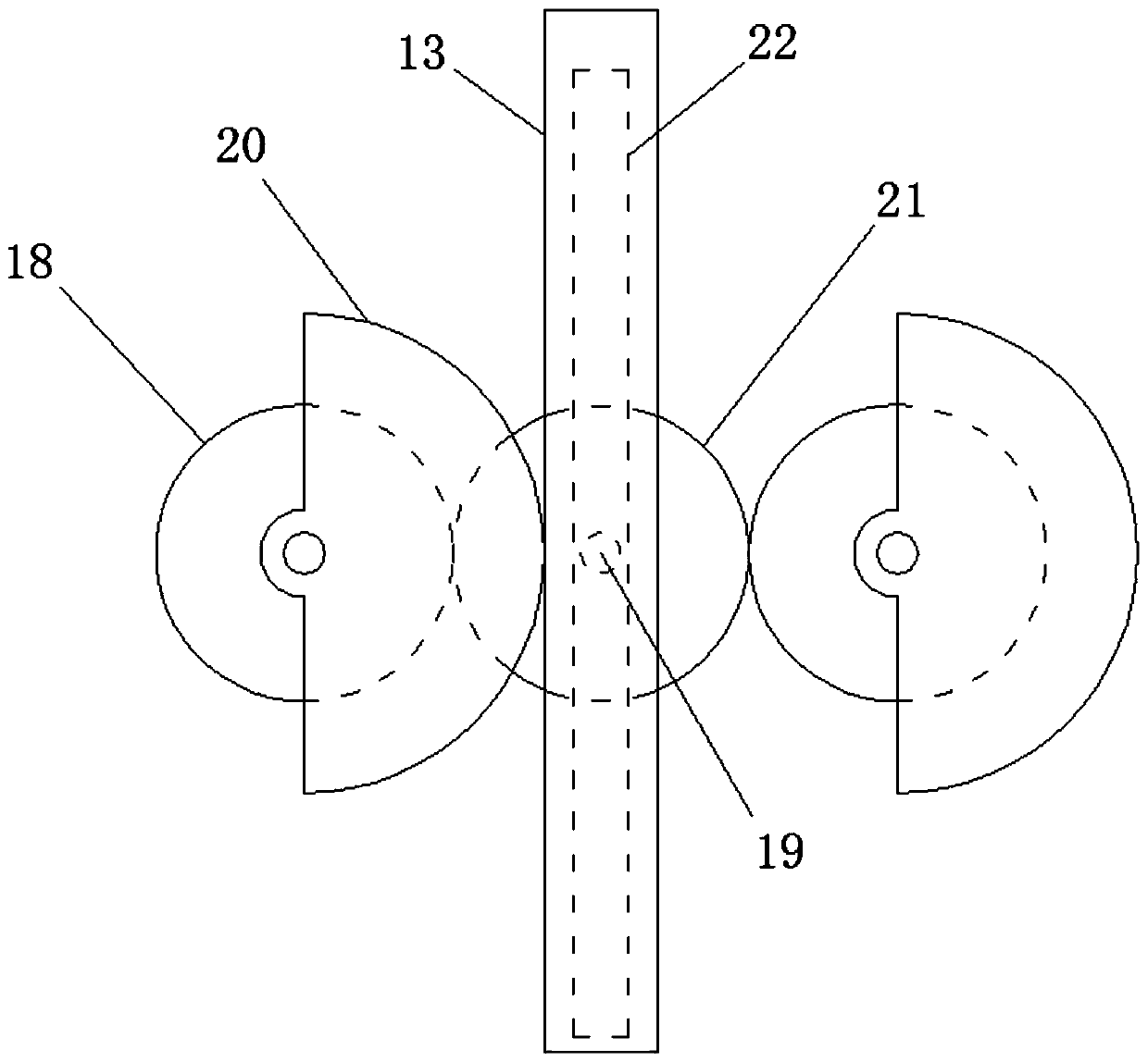
[0024] Embodiment 1: When the device is in use, the patient first sits on the chair board 2, and holds the handle 4, and then puts the head fixing bracket on the head, so that the patient's chin is in contact with the elastic rubber plate on the head fixing bracket. 12 contacts, then press the switch on the handle 4, so that the switch turns on the drive motor 17, the drive motor 17 drives the rotating rod 19 to rotate, and the rotating rod 19 will drive the main gear plate 21 to rotate after being decelerated by the reducer, and the main gear plate 21 The tooth block on the sub-gear plate 18 engages, so that the sub-gear plate 18 drives the traction gear 20 to rotate. When the tooth block on one side of the traction gear 20 engages with the tooth block on the traction plate 13, The traction plate 13 moves downward, and simultaneously the traction plate 13 drives the cross bar 14 and the slide block 15 to move downward, and the slide block 15 slides inside the chute 16, while t...

Embodiment 2

[0025] Embodiment 2: When the head fixation can not be placed on the patient's head, it is necessary to adjust the head fixation at this time, first turn the adjustment screw 25 on the side wall of the bracket 10, so that the end of the adjustment screw 25 is aligned with the side wall. The plate 11 is separated, so that the side plate 11 can be slid inside the adjustment groove 24 inside the bracket 10, so that the overall length of the head support is adjusted. part against the side plate 11, thereby fixing the head fixing bracket as a whole, and then carry out the operation steps in the first embodiment.


PUM


Abstract

The invention discloses an automatic cervical vertebra rehabilitation traction chair and relates to the field of medical rehabilitation. Aiming at the problem that the cervical vertebra rehabilitationcycle is long since cervical vertebra rehabilitation operation is not conveniently implemented for a cervical vertebra patient, the invention discloses the scheme that the chair comprises chair legs,a chair plate, a backrest plate and a handle, wherein a connecting rod is rotationally mounted at the top end of the backrest plate; a transverse plate is fixedly connected with the top end of the connecting rod; a first guide wheel is rotationally mounted on the transverse plate; the first guide wheel is arranged close to the front end of the transverse plate; and a second guide wheel is rotationally mounted on the back side of the transverse plate. By adopting the chair, cervical vertebra rehabilitation training operation of a patient can be assisted, the physical power of the patient can be saved, and meanwhile, no labor resource is taken; in addition, the patient can be prevented from toppling over; a face fixing support rack can be adjusted, so that the device can be adaptive to patients of different head shapes to implement cervical vertebra rehabilitation training operation, the practicability of the device is improved, the rehabilitation cycle of the patient can be shortened,and popularization can be benefited.

Description

technical field [0001] The invention relates to the field of medical rehabilitation, in particular to an automatic cervical spine rehabilitation traction chair. Background technique [0002] In order to shorten the rehabilitation period of cervical spine, cervical spine patients generally undergo cervical spine rehabilitation training after completing surgical treatment. For safety reasons, it is generally necessary to perform rehabilitation training through the patient's own strength during cervical spine rehabilitation treatment, and the nearby The medical staff or relatives and friends will assist to prevent the patient from relapsing due to excessive force, and the patient's own strength will consume the patient's physical strength during the training process. Therefore, in order to solve such problems, we propose an automatic cervical spine Rehabilitation traction chair. Contents of the invention [0003] The automatic cervical spine rehabilitation traction chair pro...

Claims


Application Information

Patent Timeline
Patent Type & Authority Applications(China)
IPC IPC(8): A61F5/042A61H1/02
CPCA61F5/042A61H1/0218A61H1/0296A61H2205/04
Inventor 田静娟刘芬之焦瑞娜杨玉霞刘晓燕
Owner LUOYANG ORTHOPEDIC TRAUMATOLOGICAL HOSPITAL
Why Eureka
Try Eureka