
Electronic equipment mounting cabinet with anti-collision function

A technology for electronic equipment and installation cabinets, which is applied in the field of electronic equipment installation cabinets with anti-collision functions, can solve the problems of electronic equipment damage, nowhere to store electronic equipment, and poor operation of equipment, so as to protect the top of the cabinet and avoid damage Effect

Inactive Publication Date: 2020-05-12
薛成
View PDF0 Cites 0 Cited by
  • Summary
  • Abstract
  • Description
  • Claims
  • Application Information

AI Technical Summary

Problems solved by technology

[0002] With the rapid development of science and technology, more and more electronic devices appear in people's lives. These electronic devices bring great convenience to people's lives, but the existence of more and more electronic devices also brings many troubles. , Many electronic devices have no place to store, and many electronic devices have precision parts. If they are accidentally dropped, the electronic devices will be damaged or the precision parts will be loose, resulting in poor operation of the equipment. The existing electronic device storage does not have a certain anti-collision function. It is easier to damage the internal electronic equipment under the action of external force

Method used


Image

  • Electronic equipment mounting cabinet with anti-collision function
  • Electronic equipment mounting cabinet with anti-collision function
  • Electronic equipment mounting cabinet with anti-collision function

Examples


Embodiment Construction

[0019] The following will clearly and completely describe the technical solutions in the embodiments of the present invention with reference to the accompanying drawings in the embodiments of the present invention. Obviously, the described embodiments are only some of the embodiments of the present invention, not all of them. Based on the embodiments of the present invention, all other embodiments obtained by persons of ordinary skill in the art without making creative efforts belong to the protection scope of the present invention.

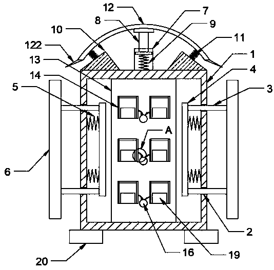
[0020] see Figure 1-5 , the present invention provides a technical solution: an electronic equipment installation cabinet with an anti-collision function, including a cabinet body 1, and movable holes 2 are respectively opened on both sides of the cabinet body 1, and the movable holes 2 A guide column 3 is installed on the inner side movably, and a connection plate 4 is fixedly arranged at one end of the guide column 3 close to the cabinet body ...


PUM


Abstract

The invention discloses an electronic equipment mounting cabinet with an anti-collision function. The electronic equipment mounting cabinet comprises a cabinet body, wherein movable holes are formed in the two ends of the surfaces of the two sides of the cabinet body correspondingly, guide columns are movably mounted on the inner sides of the movable holes, a connecting plate is fixedly arranged at one end, close to the cabinet body, of the guide column, a first spring is fixedly arranged between the connecting plate and the inner side wall of the cabinet body, a buffer plate is fixedly arranged at the end, away from the connecting plate, of the guide column, an installation cylinder is fixedly arranged in the middle of the upper end of the cabinet body, a movable column is movably installed on the inner side of the installation cylinder, a second spring is fixedly arranged between the movable column and the bottom end of the inner side of the installation cylinder, and installation members are fixedly arranged on the two sides of the installation cylinder at the upper end of the cabinet body respectively. According to the invention, external force on the cabinet body is relieved through the first spring to achieve the anti-collision purpose, and the second spring and the third spring are compressed through the protection plate, so that the external force or the falling force of heavy objects is relieved so as to achieve the buffering purpose.

Description

technical field [0001] The invention relates to the technical field of electronic equipment installation cabinets, in particular to an electronic equipment installation cabinet with an anti-collision function. Background technique [0002] With the rapid development of science and technology, more and more electronic devices appear in people's lives. These electronic devices bring great convenience to people's lives, but the existence of more and more electronic devices also brings many troubles. , Many electronic devices have no place to store, and many electronic devices have precision parts. If they are accidentally dropped, the electronic devices will be damaged or the precision parts will be loose, resulting in poor operation of the equipment. The existing electronic device storage does not have a certain anti-collision function. It is relatively easy to cause damage to the internal electronic equipment under the action of external force. Contents of the invention ...

Claims


Application Information

Patent Timeline
Patent Type & Authority Applications(China)
IPC IPC(8): H05K5/02H05K7/02H05K7/14
CPCH05K5/0217H05K7/02H05K7/14
Inventor 薛成
Owner 薛成
Learn More