


Quick Research
Generate reliable direction feasibility study reports for your R&D in just a few steps.

Technical Q&A
Discover and master advanced knowledge NOW. Basics, ideas, possibilities, all at once.

Find Solutions
As an expert in R&D theories, this can generate solutions to your technical problems instantly.

Evaluate Feasibility
Analyze your overall solution with one click, know your potential R&D risks in advance.

Monitor Landscape
Get weekly tech updates, stay abreast of the latest tech innovations and key insights.
A transmission signal receiving method and device
A technology for transmitting signals and receiving methods, which is applied in the electronic field and can solve problems such as π phase and demodulation errors, so as to avoid decoding errors or failure to decode, and improve communication efficiency
- Summary
- Abstract
- Description
- Claims
- Application Information
AI Technical Summary
Problems solved by technology
Method used
Image

Examples
Embodiment 1
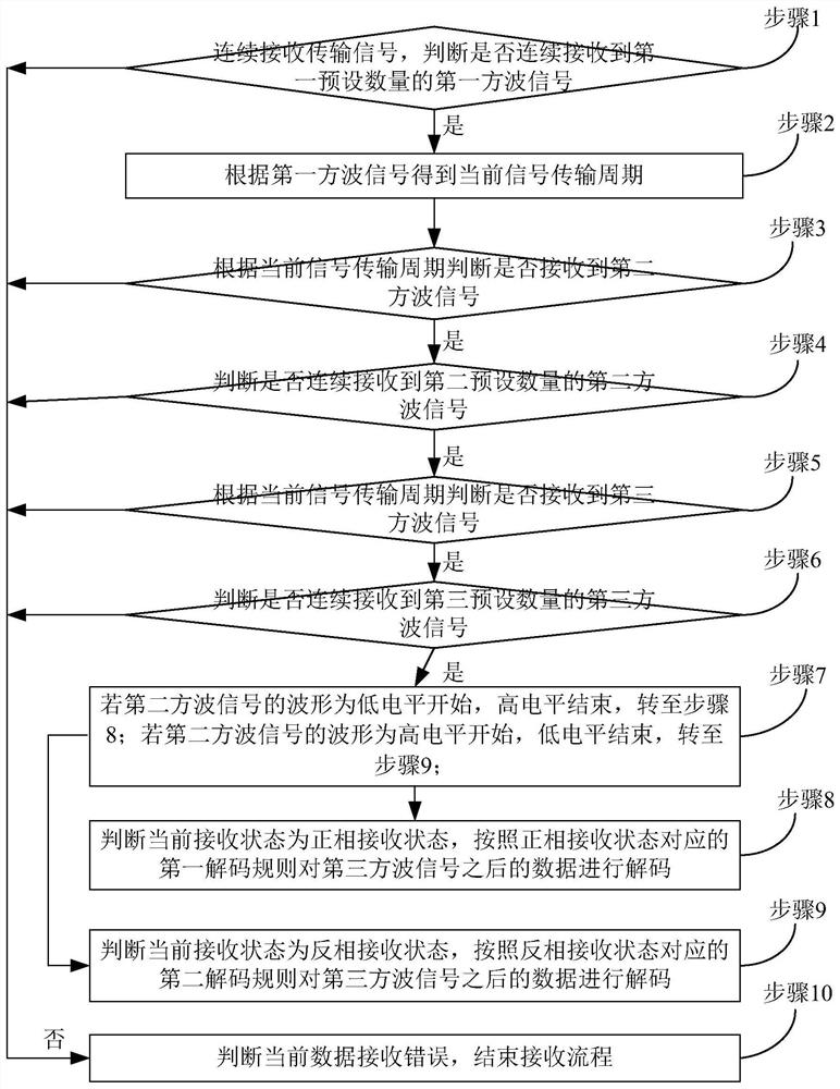
[0026] This embodiment provides a transmission signal receiving method, which can be applied in the field of power line communication. figure 1 It is a flow chart of an optional transmission signal receiving method in this embodiment.
[0027] Such as figure 1 As shown, the transmission signal receiving method mainly includes the following steps (step 1 to step 10):
[0028] Step 1, continuously receive transmission signals, and judge whether the first preset number of first square wave signals are continuously received, if yes, go to step 2, if not, go to step 10; wherein, the first square wave signal is generated by the high voltage It is composed of level signal and low level signal, and there is only one level transition.
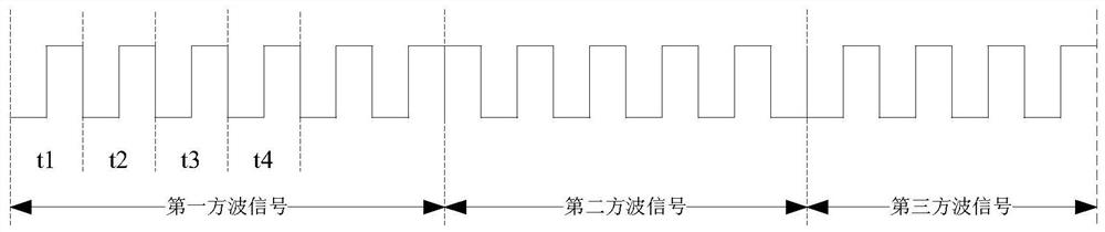
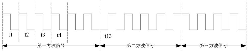
[0029] In this embodiment, the transmission signal is a square wave signal composed of a high level signal and a low level signal, the first square wave signal is a square wave signal with only one level transition, the high level signal and the low l...
Embodiment 2
[0053] This embodiment provides a transmission signal receiving device 200, which is in one-to-one correspondence with the transmission signal receiving method in Embodiment 1, and will not be repeated here, but only briefly explained. In the optional implementation of this embodiment In the manner, for the specific operations performed by each module in the transmission signal receiving device 200, reference may be made to Embodiment 1.
[0054]In this embodiment, the transmission signal receiving device 200 may be included in any communication terminal in the power line communication, for example, a camera, a PC, a server, etc., or may be an independent device.
[0055] image 3 It is a transmission signal receiving device 200 of this embodiment, including: a signal receiving module 201, a current signal transmission cycle calculation module 202, a square wave signal judging module 203 and a decoding module 204, wherein,
[0056] The signal receiving module 201 is used to c...
PUM
 Abstract
Description
Claims
Application Information
 - R&D Engineer
- R&D Manager
- IP Professional
- Industry Leading Data Capabilities
- Powerful AI technology
- Patent DNA Extraction
Browse by: Latest US Patents, China's latest patents, Technical Efficacy Thesaurus, Application Domain, Technology Topic, Popular Technical Reports.
© 2024 PatSnap. All rights reserved.Legal|Privacy policy|Modern Slavery Act Transparency Statement|Sitemap|About US| Contact US: help@patsnap.com