Demodulation circuit of non-contact IC card

A demodulation circuit, non-contact technology, applied in the field of non-contact IC card demodulation circuit, can solve the problems of low input signal VREF3, decoding error, affecting normal transmission of data bits, etc., to improve sensitivity, realize decoding, The effect of preventing decoding errors

Active Publication Date: 2016-10-19
SHANGHAI HUAHONG GRACE SEMICON MFG CORP
View PDF4 Cites 0 Cited by
  • Summary
  • Abstract
  • Description
  • Claims
  • Application Information

AI Technical Summary

Problems solved by technology

[0012] like figure 1 As shown, the second input terminal of the comparator 106 is biased by the bias circuit 107, when the groove signal in the input modulated signal arrives, the input signal VREF3 needs to be pulled low, in order to When the electromagnetic field emitted by the card reader is strong, the input signal VREF3 needs to be quite sensitive to the groove signal in the modulated signal, so the DC bias drive of the bias circuit 107 cannot be too strong at this time; When the groove signal is recovered, if the DC bias drive of the bias circuit 107 is kept too small, the recovery of the input signal VREF3 will be very slow, which will affect the normal transmission of the next data bit
Especially for non-contact IC cards with a transmission rate of 848kbits / s, the transmission time Tbit of one data bit is only 16clk, and it is usually necessary to control the groove signal in the modulated signal within 8clk, so when the groove signal in the modulated signal When the slot signal recovers, the recovery time for the input signal VREF3 to return to the normal value can only be maintained within 16clk-8clk=8clk. When the recovery time exceeds the above-mentioned period, it will cause decoding errors
Because the DC bias drive of the bias circuit 107 in the prior art is too small, when the manufacturing process conditions of the non-contact IC card and the magnitude of the magnetic field induced are different, decoding errors are easy to occur, so the existing non-contact IC card It is difficult for the demodulation circuit to correctly decode the full process conditions and full field strength conditions

Method used


Image

  • Demodulation circuit of non-contact IC card
  • Demodulation circuit of non-contact IC card
  • Demodulation circuit of non-contact IC card

Examples


Embodiment Construction

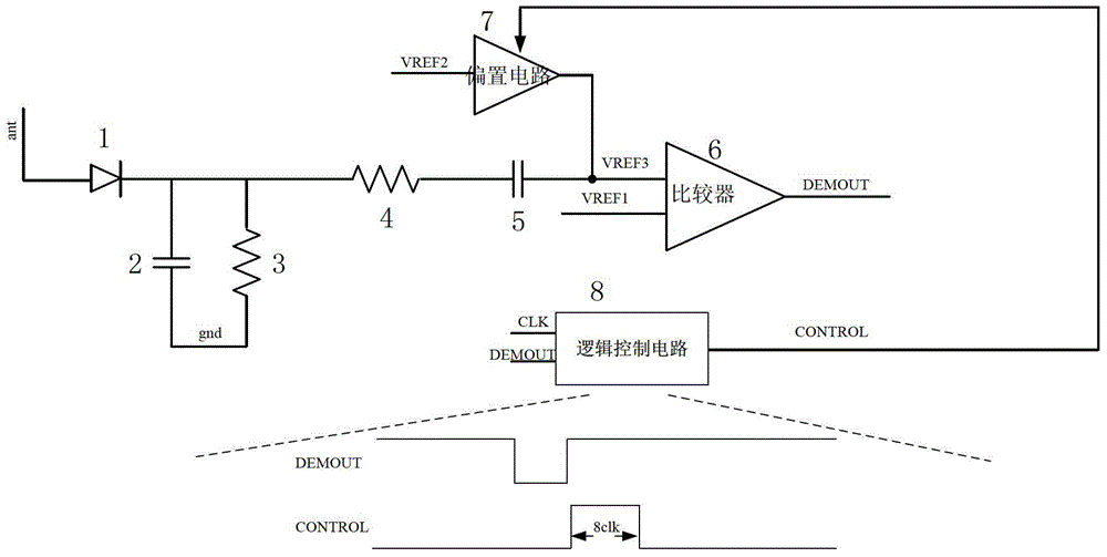
[0025] Such as image 3 Shown is the schematic diagram of the demodulation circuit of the non-contact IC card of the embodiment of the present invention; In the demodulation circuit of the non-contact IC card of the embodiment of the present invention, the carrier frequency of the transmission data from the card reader to the non-contact IC card is 13.56 MHZ, the data transmission rate is 848Kbits / s, and the transmission time Tbit of one data bit is 16clk. The demodulation circuit includes:

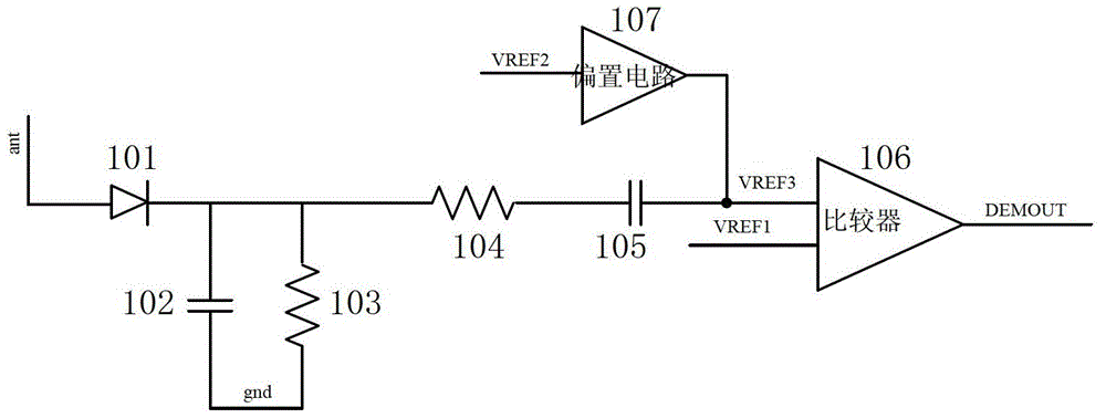
[0026] Comparator 6, the first input end of described comparator 6 is connected with first reference signal VREF1, and the second input end of described comparator 6 is connected with input signal VREF3, and this input signal VREF3 is described non-contact IC card from antenna namely image 3 The modulated signal emitted by the card reader received at the middle ant is a signal after detection and high-pass filtering; the output terminal of the comparator 6 outputs a demodulated signal D...


PUM


Abstract

Disclosed in the invention is a demodulation circuit of a non-contact IC card. The demodulation circuit comprises a comparator, a bias circuit and a logic control circuit. The input terminal of the logic control circuit is connected with a clock signal and a demodulation signal outputted by the comparator and the logic control circuit outputs a control signal to the bias circuit. The logic control circuit starts to output an eight-clock period high level at a rising edge when a groove signal of the demodulation signal is converted into a high level and the driving capability of the bias circuit is enhanced by the high level, so that self-adapting adjustment of the driving capability of the bias circuit based on the output of the demodulation circuit can be realized. Therefore, sensitivity of groove signal sensing in the modulated signal can be improved; and the input terminal of the demodulation circuit can be recovered rapidly after recovery of the groove signal in the modulated signal, thereby realizing correct decoding of the demodulation circuit on the full-process condition and the full-field intensity condition.

Description

technical field [0001] The invention relates to a semiconductor integrated circuit, in particular to a demodulation circuit of a non-contact IC card. Background technique [0002] Between the non-contact IC card and the card reader, the radio frequency signal is used as a carrier to transmit information. The non-contact IC card itself has no power supply, and its working power is provided by the radio frequency signal of the card reader, and the radio frequency signal of the card reader is 13.56MHz. When the card reader and the non-contact IC card transmit data, the carrier is a 13.56MHz radio frequency carrier, and the signal transmission rates are 106kbits / s, 212kbits / s, 424kbits / s, and 848k bits / s. [0003] Among them, when transmitting data from the card reader to the non-contact IC card, the amplitude keying (ASK) method is used to modulate the signal, and the encoding method is synchronous and improved Miller (miller) encoding. When the card reader and the non-contac...

Claims


Application Information

Patent Timeline
Patent Type & Authority Patents(China)
IPC IPC(8): G06K19/073G06K7/00
Inventor 唐成伟陈涛
Owner SHANGHAI HUAHONG GRACE SEMICON MFG CORP
Why Eureka
Try Eureka