System and method for detecting bearing capacity of all-round mechanical and electrical integration foundation pile
A detection system and bearing capacity technology, which is applied in the direction of foundation structure engineering, foundation structure test, construction, etc., can solve the problems of cumbersome assembly or disassembly of components, low accuracy of absolute displacement measurement of foundation piles, low work efficiency, etc., and achieve pressure Uniform, not easy to damage, reduce the effect of work intensity
- Summary
- Abstract
- Description
- Claims
- Application Information
AI Technical Summary
Problems solved by technology
Method used
Image
Examples
Embodiment 1
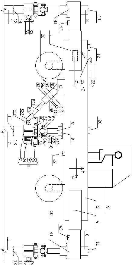
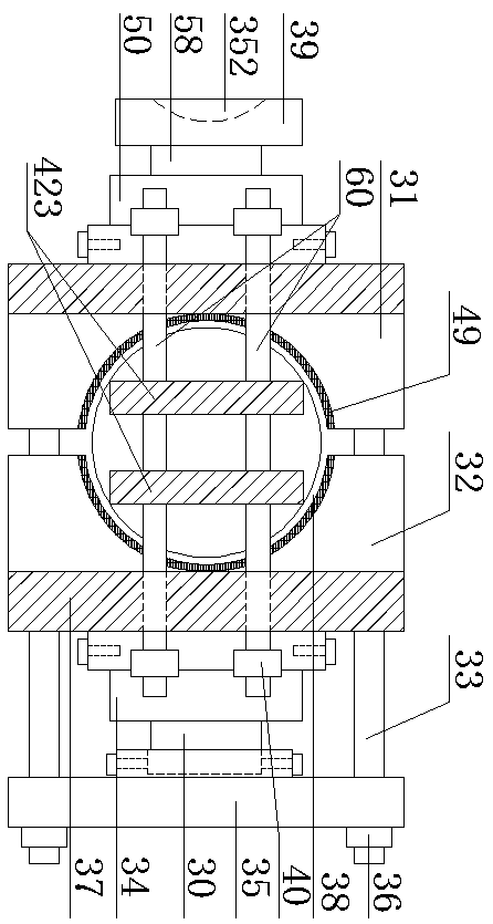
[0070] Example 1: (1), such as Figure 1 to Figure 7 An electromechanical three-position integrated foundation pile bearing capacity detection system is shown, including a reaction force system, a displacement measurement system, and a loading system. The reaction force system and the loading system are integrally connected, and the reaction force system includes an anchor pile 1, Cross beam 2, hydraulic hoop 3, support arm 4, horizontal reaction device 5, support 6, foundation pile 7, inverted hydraulic cylinder A8, located on the left and right sides of the front and rear sides of the cross beam 2 A support arm 4 is rotatably connected. The outermost end of the support arm 4 and the bottom of the center of the beam 2 are both fixed with a hydraulic cylinder A8. The ends of the hydraulic cylinder A8's ejector rod are all ball-articulated to the support 6, and the support 6 is double-pinned. The shaft 60 is movably connected with the hydraulic hoop 3; anchor piles 1 are inserte...
Embodiment 2
[0096] Example 2: Such as figure 1 , Figure 7 The illustrated support arm 4 can be extended or shortened to adapt to the pile position arrangement of the anchor pile 1 in different sites, and the anchor pile 1 around the foundation pile 7 can be better utilized, and the applicability is strong.
Embodiment 3
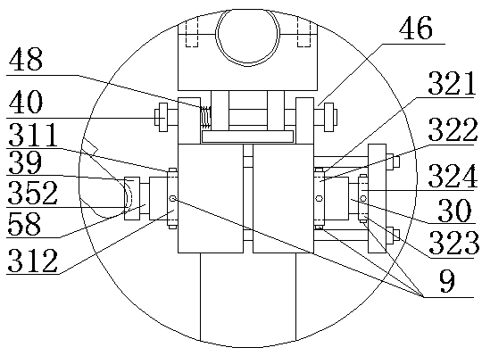
[0097] Example 3: Such as figure 2 As shown, when the hydraulic jack K34 is loaded to the right, there is a gap 46 between the limit nut 40 and the support vertical plate 37 on the same side, which is convenient for the loosening of the left holding plate 31 and the right holding plate 32 after the inspection is completed. It is convenient to unload the hydraulic hoop 3 as a whole. At the same time, a spring 48 is sleeved on the double pin shaft 60 between the left support vertical plate 37 and the left limit vertical plate 63, so that the left holding plate 31 and the right holding plate 32 It is easier to separate, which further facilitates the unloading of the hydraulic hoop 3 as a whole.
PUM
 Abstract
Description
Claims
Application Information
 - R&D Engineer
- R&D Manager
- IP Professional
- Industry Leading Data Capabilities
- Powerful AI technology
- Patent DNA Extraction
Browse by: Latest US Patents, China's latest patents, Technical Efficacy Thesaurus, Application Domain, Technology Topic, Popular Technical Reports.
© 2024 PatSnap. All rights reserved.Legal|Privacy policy|Modern Slavery Act Transparency Statement|Sitemap|About US| Contact US: help@patsnap.com


