A transmission system and signal transmission method of an Ethernet physical layer signal
A physical layer signal and transmission system technology, applied in the field of Ethernet physical layer signal transmission system, can solve problems such as increasing device cost, and achieve the effect of reducing implementation cost, layout and wiring space
- Summary
- Abstract
- Description
- Claims
- Application Information
AI Technical Summary
Problems solved by technology
Method used
Image

Examples
Embodiment 1
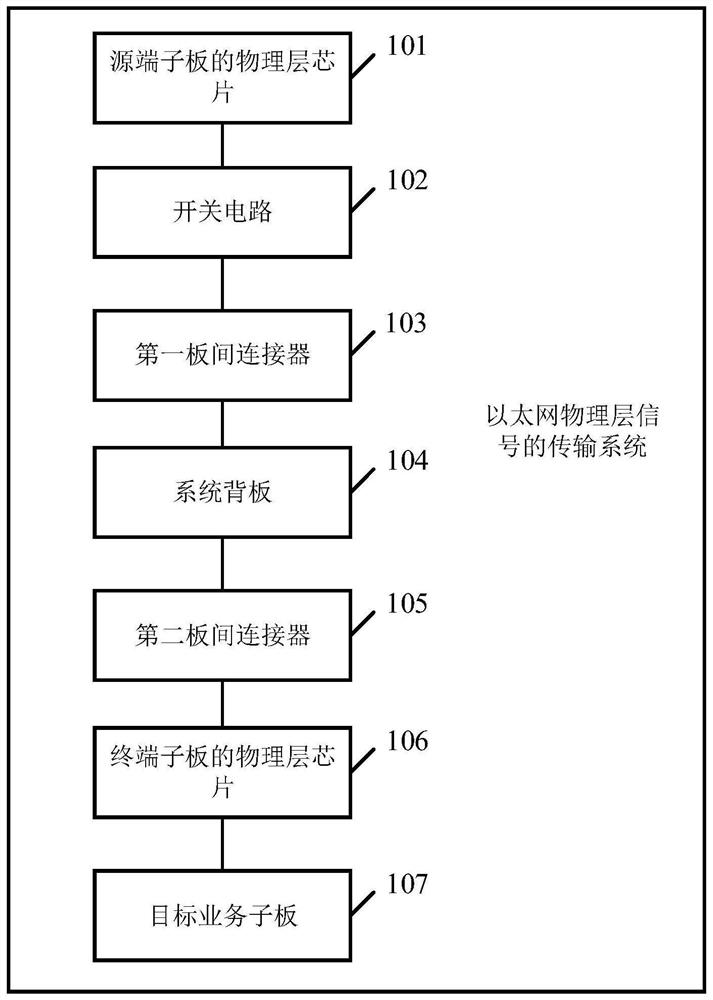
[0023] Such as figure 1 Distance figure 1 A structural schematic structural diagram of a transmission system of an Ethernet physical layer signal disclosed in this example, the system can include a physical layer chip 101, a switching circuit 102, a first panel connector 103, a system backplane 104 , The second panel connector 105, the physical layer chip 106 and the target operation subboard 107, wherein:
[0024] The physical layer chip 101 of the source terminal plate is configured to transmit a physical layer signal to the switch circuit 102.
[0025] In the embodiment of the present invention, the source terminal may be any piece of Ethernet development motherboard for transmitting a physical layer signal. The Ethernet development motherboard can be configured with a physical layer chip or other component; wherein the physical layer chip can be an operation open. The physical layer device of the Open System Interconnection Reference Model (OSI), the physical layer chip can be...
Embodiment 2
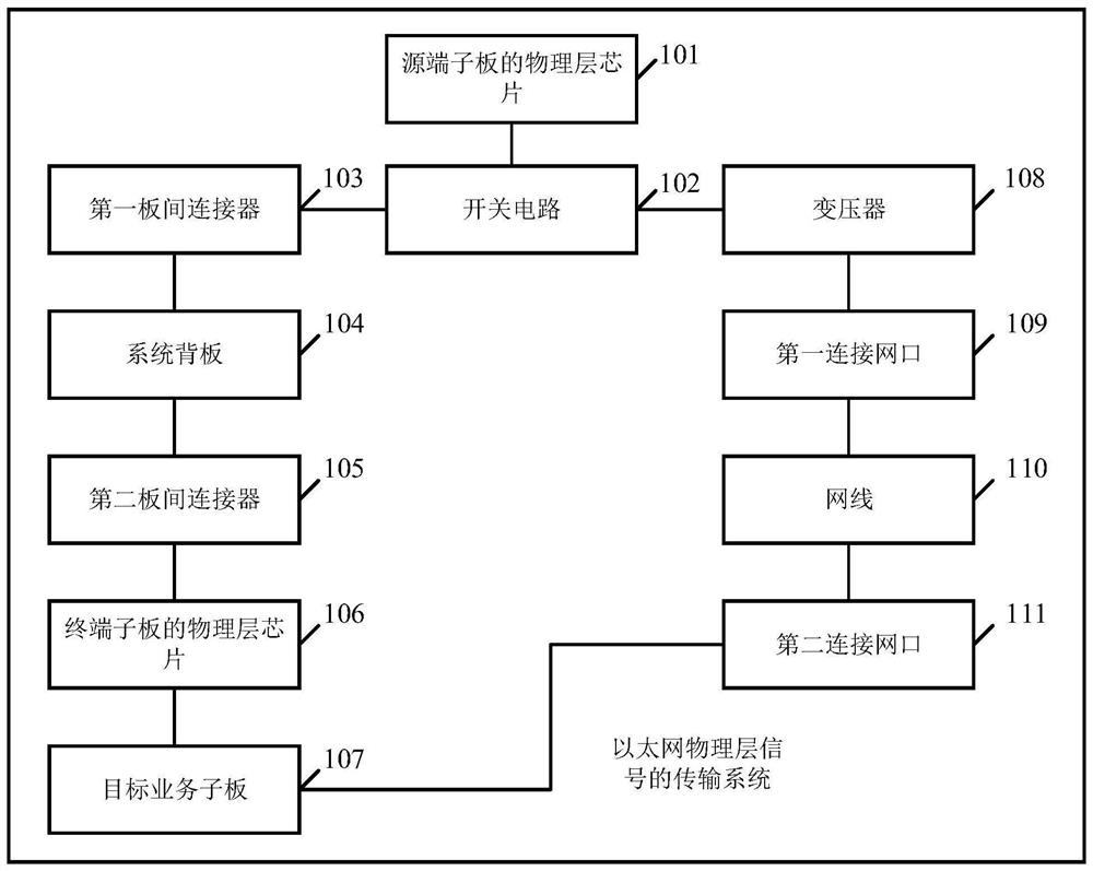
[0051] Such as figure 2 Distance figure 2 A structural diagram of the transmission system of another Ethernet physical layer signal disclosed in this example, figure 2 The system shown is figure 1 The system shown is optimized, with figure 1 The system shown is compared, figure 2 The system shown is also included in the transformer 108, the first connection network port 109, the network cable 110, and the second connection network port 111, where:
[0052] The switching circuit 102 is further configured to forward the physical layer signal to the transformer 108 when it is determined that the extent of the active terminal plate is not connected to the system backplane 104 by the first panel connector 103.
[0053] In the embodiment of the present invention, the switching circuit 102 may also be forwarded to the transformer 108 when it is further determined by the above-described logic circuit to be connected to the system back plate 104 by the first panel connector 103.
[0054] T...
Embodiment 3
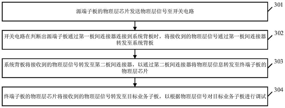
[0070] Such as image 3 Distance image 3 It is a flow diagram of a signal transmission method disclosed in the embodiment of the present invention, which is applied to figure 1 The transmission system of the Ethernet physical layer signal, the system can include: a physical layer chip, a switch circuit, a first plate, a system back panel, a second panel connector, a terminal panel Physical layer chips and target operators, the signal transmission method can include the following steps:
[0071] 301. The physical layer chip of the source terminal is transmitted to the physical layer signal to the switching circuit.
[0072] As an alternative embodiment, the transmission system of the Ethernet physical layer signal can also include a preset anti-interference device, and the source terminal panel before transmitting a physical layer signal to the physical layer signal from the physical layer signal of the source terminal. The physical layer chip can also determine whether the model of...
PUM
 Abstract
Description
Claims
Application Information
 - Generate Ideas
- Intellectual Property
- Life Sciences
- Materials
- Tech Scout
- Unparalleled Data Quality
- Higher Quality Content
- 60% Fewer Hallucinations
Browse by: Latest US Patents, China's latest patents, Technical Efficacy Thesaurus, Application Domain, Technology Topic, Popular Technical Reports.
© 2025 PatSnap. All rights reserved.Legal|Privacy policy|Modern Slavery Act Transparency Statement|Sitemap|About US| Contact US: help@patsnap.com