


Quick Research
Generate reliable direction feasibility study reports for your R&D in just a few steps.

Technical Q&A
Discover and master advanced knowledge NOW. Basics, ideas, possibilities, all at once.

Find Solutions
As an expert in R&D theories, this can generate solutions to your technical problems instantly.

Evaluate Feasibility
Analyze your overall solution with one click, know your potential R&D risks in advance.

Monitor Landscape
Get weekly tech updates, stay abreast of the latest tech innovations and key insights.
Side surface direct insertion type wiring terminal
A terminal, in-line technology, applied in the direction of connection, conductive connection, clamping/spring connection, etc., can solve the problems of installation and disassembly, and achieve the effect of convenient use
- Summary
- Abstract
- Description
- Claims
- Application Information
AI Technical Summary
Problems solved by technology
Method used
Image

Examples
Embodiment 1
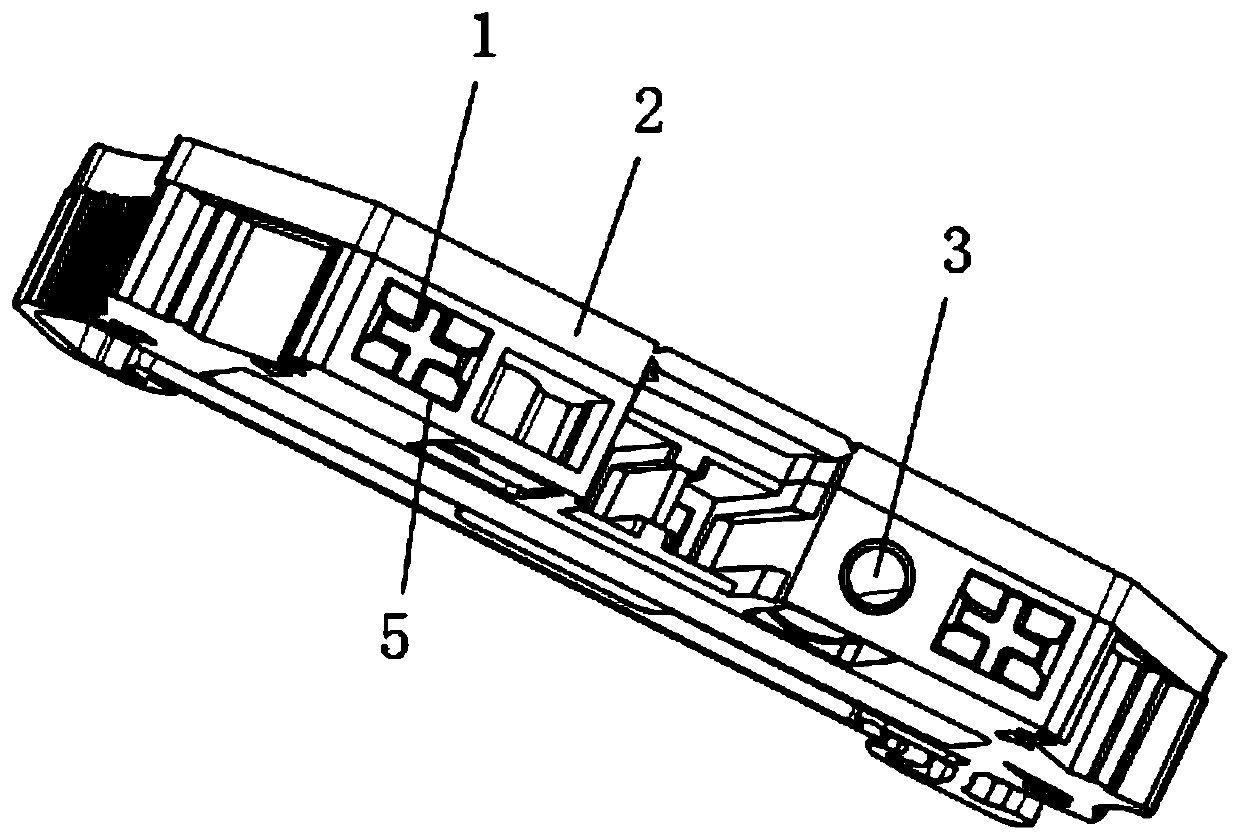
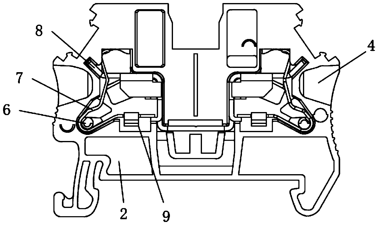
[0029] This embodiment provides a specific structure of a side in-line terminal, such as figure 1 As shown in -6, it includes a casing 2 with wire insertion holes 4 at both ends and a conductive member 8 arranged inside the casing 2 for conducting electricity. The shrapnel 7, one end of the shrapnel 7 is fixed by the buckle 9;
[0030] The top of the housing 2 is provided with a key hole 5, and a key 1 is arranged inside the key hole 5, and the key 1 can move vertically in the key hole 5, and the bottom of the key 1 is in contact with one end of the shrapnel 7, and the key 1 1 When moving in the vertical direction, the elastic piece 7 can be squeezed to generate deformation, and the elastic piece 7 can realize the fixing and releasing of the insert inserted in the wire insertion hole 4 during the deformation process.
[0031] By adopting the above technical solutions:
[0032] When the connector is inserted into the wire insertion holes 4 at both ends of the housing 2, the c...
Embodiment 2
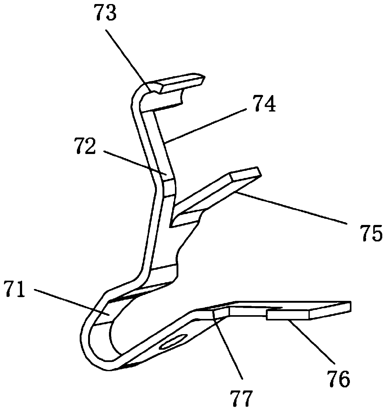
[0034] This embodiment provides a specific structure of a side in-line terminal, such as figure 1 As shown in -3, the elastic piece 7 includes a first deformation part 71 in a U-shaped structure and a second deformation part 72 connected to one end of the first deformation part 71, and the second deformation part 72 is directed toward the vertical end of the first deformation part 71. The other end of the first deformation part 71 is connected to the first end part 76, the other end of the second deformation part 72 is connected to the second end part 73, and the inner wall of the housing 2 is located at the bending position of the first deformation part 71. There is a blocking column 6, the blocking column 6 adopts a cylindrical structure, and the first deformation part 71 can deform around the blocking column 6;
[0035] A second groove 74 is provided below the second deforming portion 72, and an insertion piece 75 is provided at one end of the second groove 74. The insertio...
PUM
 Abstract
Description
Claims
Application Information
 - R&D Engineer
- R&D Manager
- IP Professional
- Industry Leading Data Capabilities
- Powerful AI technology
- Patent DNA Extraction
Browse by: Latest US Patents, China's latest patents, Technical Efficacy Thesaurus, Application Domain, Technology Topic, Popular Technical Reports.
© 2024 PatSnap. All rights reserved.Legal|Privacy policy|Modern Slavery Act Transparency Statement|Sitemap|About US| Contact US: help@patsnap.com