
Image processing device and near-to-eye imaging apparatus

An image processing device, imaging equipment technology, applied in optical components, optics, instruments, etc., can solve the problems of small field of view, low light efficiency, small field of view and eye movement range, etc., to increase the eye movement range , the effect of large field of view

Pending Publication Date: 2020-05-08
ZHEJIANG CRYSTAL OPTECH
View PDF0 Cites 1 Cited by
  • Summary
  • Abstract
  • Description
  • Claims
  • Application Information

AI Technical Summary

Problems solved by technology

The near-eye imaging device is composed of an optical machine and a waveguide. Although the range of eye movement can be increased, the field of view is small, the light efficiency is low, and the color quality is poor.
Combining foldback lens with OLED or LCOS screen, the field of view is limited by the size of the chip, resulting in a small field of view and eye movement range

Method used


Image

  • Image processing device and near-to-eye imaging apparatus
  • Image processing device and near-to-eye imaging apparatus
  • Image processing device and near-to-eye imaging apparatus

Examples


Embodiment 1

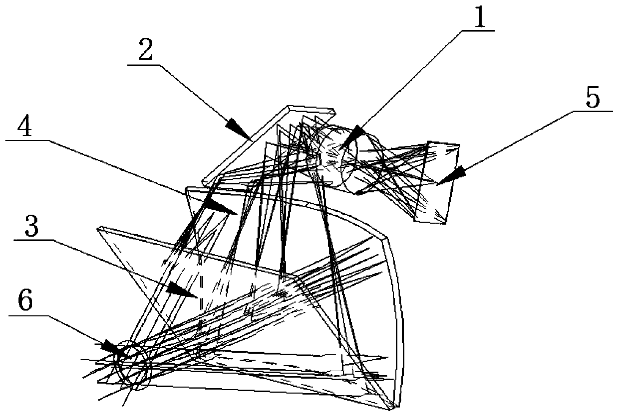
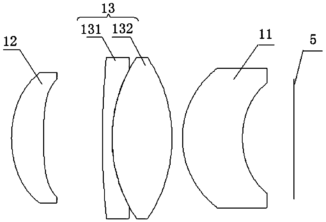
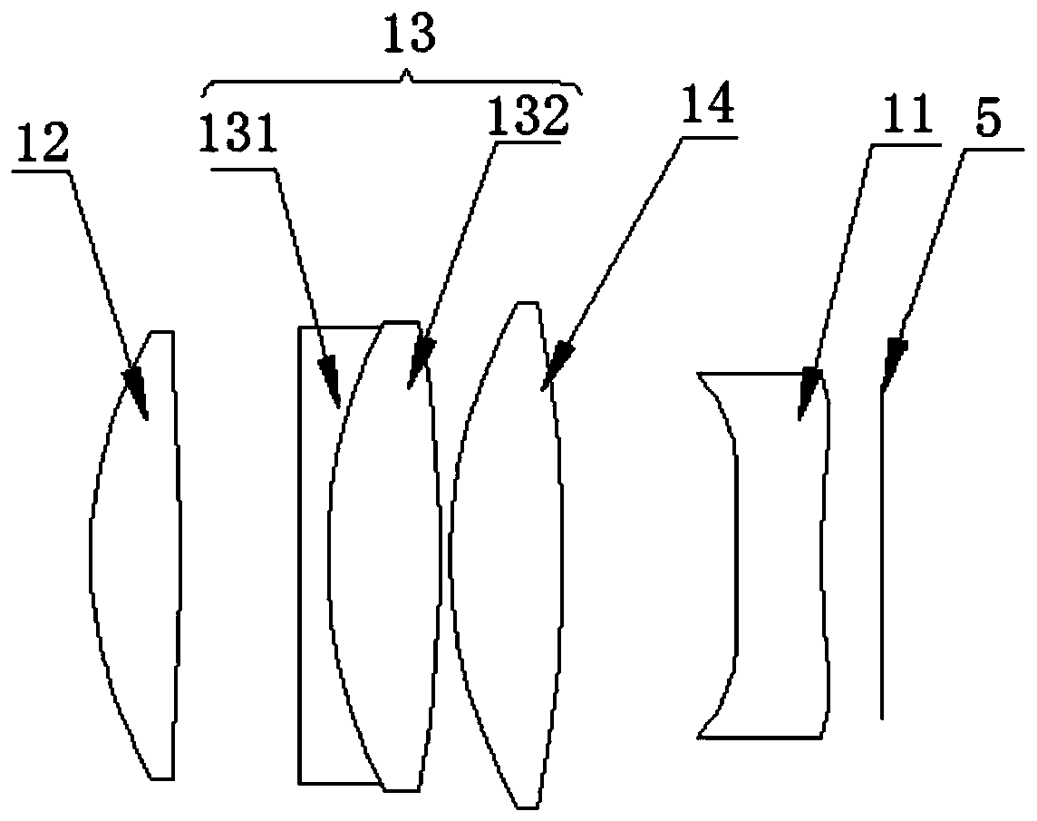
[0035] Such as figure 1 As shown, the image processing device provided by the embodiment of the present invention includes: an image magnifying component 1, a reflective component 2, a semi-reflective and semi-transparent component 3, and a partially reflective component 4; the image magnifying component 1 is used to amplify an image, and the enlarged The image is injected into the reflective component 2; the reflective component 2 is used to reflect the image to the semi-reflective and semi-transparent component 3; the image injected into the semi-reflective and semi-transparent component 3 through the reflective component 2 is reflected to the partially reflective component by the semi-reflective and semi-transparent component 3 4. The image processed by the partially reflective component 4 is transmitted through the semi-reflective and semi-transparent component 3.

[0036] Specifically, the image magnifying component 1 can magnify the image generated by the image source 5 for ...

Embodiment 2

[0051] Such as Image 6 As shown, the near-eye imaging device provided by the embodiment of the present invention includes: a first optical imaging device and a second optical imaging device. Both the first optical imaging device and the second optical imaging device include: the image source 5 and the one provided in the first embodiment. In the image processing device, the image from the image source 5 is injected into the image magnifying component 1.

[0052] Specifically, the near-eye imaging device can be configured as a head-mounted display system, and the near-eye imaging device has the same technical effect as the image processing device, so it will not be repeated here. It should be noted that the image source 5 includes: an organic light emitting diode (OLED), a liquid crystal on silicon (LCOS), a micro LED (micro LED), or a digital micro mirror (DMD). If the image source 5 uses a silicon-based liquid crystal or a digital micromirror, an additional lighting device is ...


PUM

PropertyMeasurementUnit
Angleaaaaaaaaaa

Abstract

The invention provides an image processing device and a near-to-eye imaging apparatus, and relates to the technical field of near-to-eye imaging. The image processing device provided by the inventioncomprises: an image amplification assembly, a reflection assembly, a semi-reflection and semi-transmission assembly and a partial reflection assembly; the image magnifying assembly is used for magnifying an image and emitting the magnified image into the reflection assembly; the reflection assembly is used for reflecting the image to the semi-reflection and semi-transmission assembly; an image emitted into the semi-reflection and semi-transmission assembly through the reflection assembly is reflected to the partial reflection assembly through the semi-reflection and semi-transmission assembly,and the image processed by the partial reflection assembly is transmitted to the semi-reflection and semi-transmission assembly. According to the image processing device provided by the invention, the image can be amplified in a smaller size space, so that the field angle and the eye movement range are increased.

Description

Technical field [0001] The present invention relates to the technical field of near-eye imaging, in particular to an image processing device and near-eye imaging equipment. Background technique [0002] The near-eye display optical system is a type of optical device that magnifies the image from the micro display and transmits it into the human eye, and allows the human eye to see the real world at the same time. The user can see the virtual image and the real image through the near-eye display optical system. The size of the field of view determines the range of the field of view. The larger the field of view, the larger the field of view and the greater the eye movement range (EYEBOX). Big. Using an optical machine and a waveguide film to form a near-eye imaging device can increase the eye movement range, but the field of view is small, the light efficiency is low, and the color quality is poor. With the combination of foldback lens and OLED or LCOS screen, the field of view ...

Claims


Application Information

Patent Timeline
IPC IPC(8): G02B27/01
CPCG02B27/0101G02B2027/0114
Inventor 吴庆利冯东洋麦英强刘风雷
Owner ZHEJIANG CRYSTAL OPTECH
Learn More