
Flange airtightness detection device

A technology of air tightness detection and flange, which is applied in the direction of liquid tightness measurement using liquid/vacuum degree, testing fluid tightness by detecting the size change of the tested structural parts, etc., which can solve the problems of slow operation, leakage of defective products, No problems such as air leakage, so as to improve the detection efficiency, meet the requirements of full inspection, and facilitate the detection

Pending Publication Date: 2020-05-08
ZHUHAI NANTE METAL TECH
View PDF0 Cites 0 Cited by
  • Summary
  • Abstract
  • Description
  • Claims
  • Application Information

AI Technical Summary

Problems solved by technology

[0002] The airtightness requirements of flange products are very strict, and air leakage is not allowed, otherwise it will affect the overall performance of machinery such as compressors. However, the existing air leakage detectors operate slowly and cannot meet the requirements of full inspection, so only Sampling inspection is possible. If full inspection is performed, the investment in personnel and equipment will seriously exceed the standard.
This method is not applicable, so random inspection is adopted, which leads to the leakage of defective products with air leakage to customers, resulting in a large number of unqualified products flowing into the market, which has a serious impact on the enterprise

Method used


Image

  • Flange airtightness detection device
  • Flange airtightness detection device
  • Flange airtightness detection device

Examples


Embodiment Construction

[0026] Embodiments of the present invention are described in detail below, examples of which are shown in the drawings, wherein the same or similar reference numerals designate the same or similar elements or elements having the same or similar functions throughout. The embodiments described below by referring to the figures are exemplary only for explaining the present invention and should not be construed as limiting the present invention.

[0027] In the description of the present invention, it should be understood that the orientation descriptions, such as up, down, front, back, left, right, etc. indicated orientations or positional relationships are based on the orientations or positional relationships shown in the drawings, and are only In order to facilitate the description of the present invention and simplify the description, it does not indicate or imply that the device or element referred to must have a specific orientation, be constructed and operated in a specific ...


PUM


Abstract

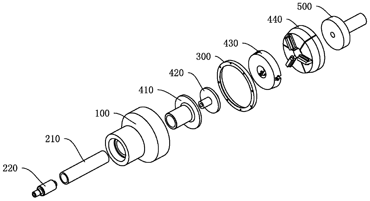
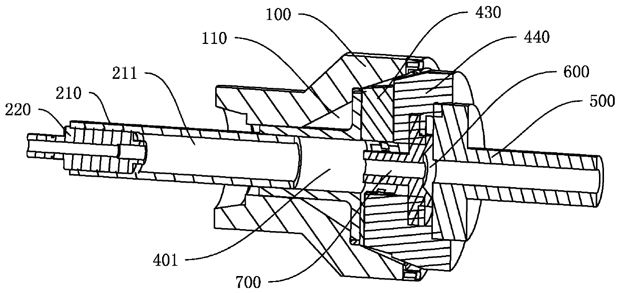
The invention discloses a flange airtightness detection device, which comprises a base, the base is provided with a conical cavity, and the axial direction of the conical cavity is provided with a through hole penetrating through the base; a detection head which comprises a pull rod which penetrates through the through hole and an air tightness detection chuck which is connected to one end of thepull rod in a sliding manner; an anti-drop structure is arranged at the joint of the pull rod and the air tightness detection chuck; the air tightness detection chuck is provided with an air tightnessdetection port arranged towards the extension direction of the pull rod. The workpiece and the air tightness detection port form a closed detection cavity, the pull rod is provided with a first concave cavity communicated with the detection cavity, the first concave cavity is communicated with the air tightness detection chuck to form an air tightness detection inner cavity with a variable volume, and the detection cavity is communicated with the air tightness detection inner cavity. The flange air tightness detection device provided by the invention can quickly judge whether the flange leaksair, greatly improves the detection efficiency, and meets the requirements of full detection.

Description

technical field [0001] The invention relates to a flange air tightness detection device, in particular to a flange air tightness detection device. Background technique [0002] The airtightness requirements of flange products are very strict, and air leakage is not allowed, otherwise it will affect the overall performance of machinery such as compressors. However, the existing air leakage detectors operate slowly and cannot meet the requirements of full inspection, so only Sampling inspection is possible, and if full inspection is performed, the investment in personnel and equipment will seriously exceed the standard. This method is not applicable, so sampling inspection is adopted, which leads to the leakage of defective products with air leakage to customers, resulting in a large number of unqualified products flowing into the market, which has a serious impact on the enterprise. Contents of the invention [0003] The present invention aims to solve at least one of the ...

Claims


Application Information

Patent Timeline
Patent Type & Authority Applications(China)
IPC IPC(8): G01M3/36
CPCG01M3/36
Inventor 邹志宏
Owner ZHUHAI NANTE METAL TECH
Learn More