Clutch device of speed reduction clutch

The technology of a clutch device and deceleration clutch, which is applied in the field of clutches, can solve the problems that plastic shift forks and positioning plates are easily deformed, there is no adjustment device to adjust, and the gap fluctuation range is large, so as to improve processing accuracy and structural stability, assembly Ease of use and the effect of improving productivity

Pending Publication Date: 2020-05-08
ZHEJIANG SANXING MECHANICAL & ELECTRONICSAL STOCK
View PDF0 Cites 0 Cited by
  • Summary
  • Abstract
  • Description
  • Claims
  • Application Information

AI Technical Summary

Problems solved by technology

However, most of the shifting forks and positioning plates of the existing shifting fork embedded clutch structure are made of plastic parts. Plastic shifting forks and positioning plates are prone to deformation and other defects after long-term use, and the assembly process is cumbersome and the production efficiency is low.
[0003] In addition, during the production of the existing shift fork jaw-type clutch structure, because the shift fork and positioning plate are plastic parts, there are processing errors and deformation, and there is no adjustment device to adjust, the gap variation range of technical requirements is large, and the defective rate higher, less practical

Method used


Image

  • Clutch device of speed reduction clutch
  • Clutch device of speed reduction clutch
  • Clutch device of speed reduction clutch

Examples


Embodiment Construction

[0020] In the description of this embodiment, it should be noted that if the terms "center", "upper", "lower", "left", "right", "vertical", "horizontal", "inner", " Outside", "front", "rear", etc., the orientation or positional relationship indicated is based on the orientation or positional relationship shown in the drawings, which is only for the convenience of describing the present invention and simplifying the description, rather than indicating or implying Any device or element must have a specific orientation, be constructed and operate in a specific orientation and, therefore, should not be construed as limiting the invention. In addition, the terms "first", "second", and "third" are used for descriptive purposes only, and should not be understood as indicating or implying relative importance.

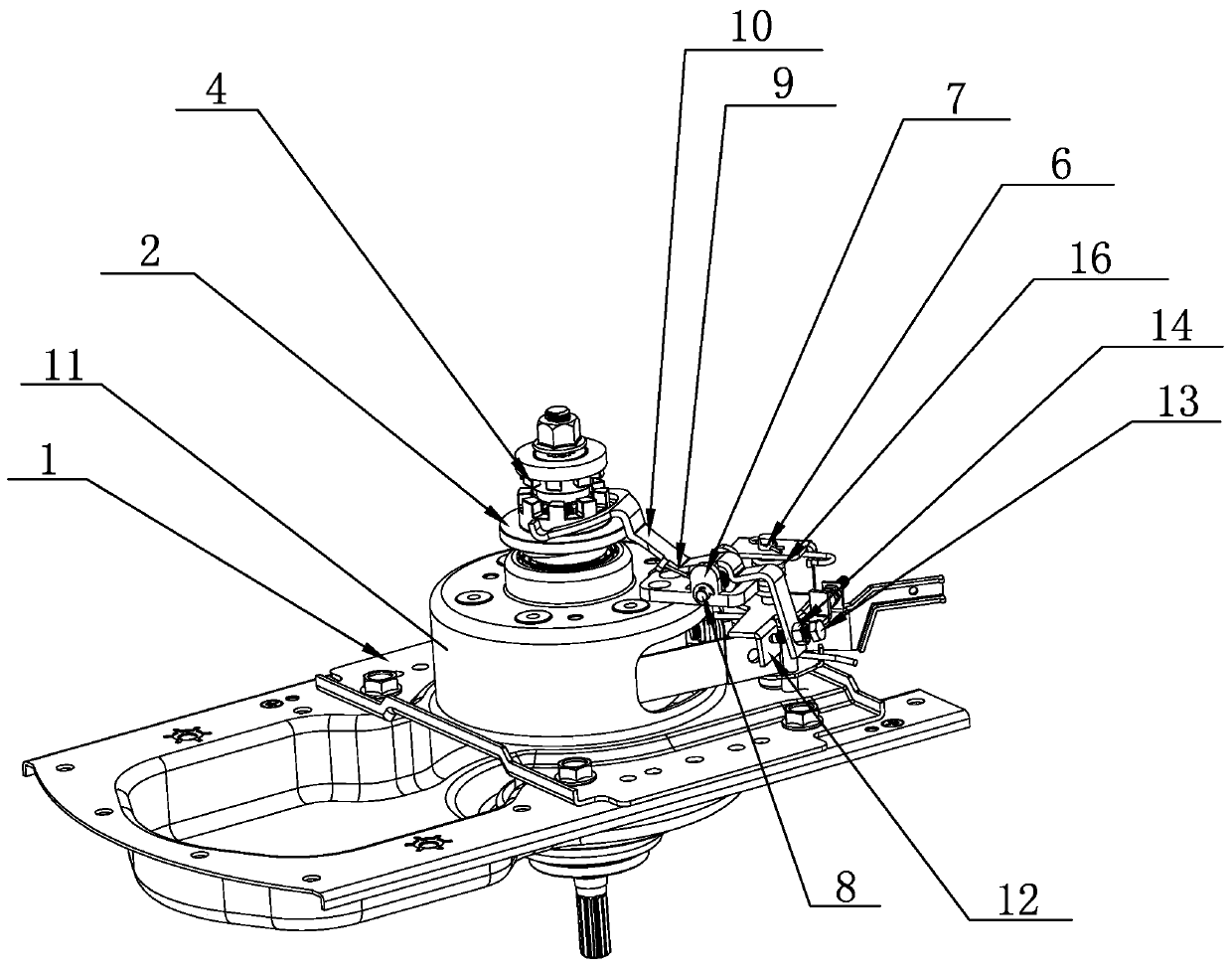
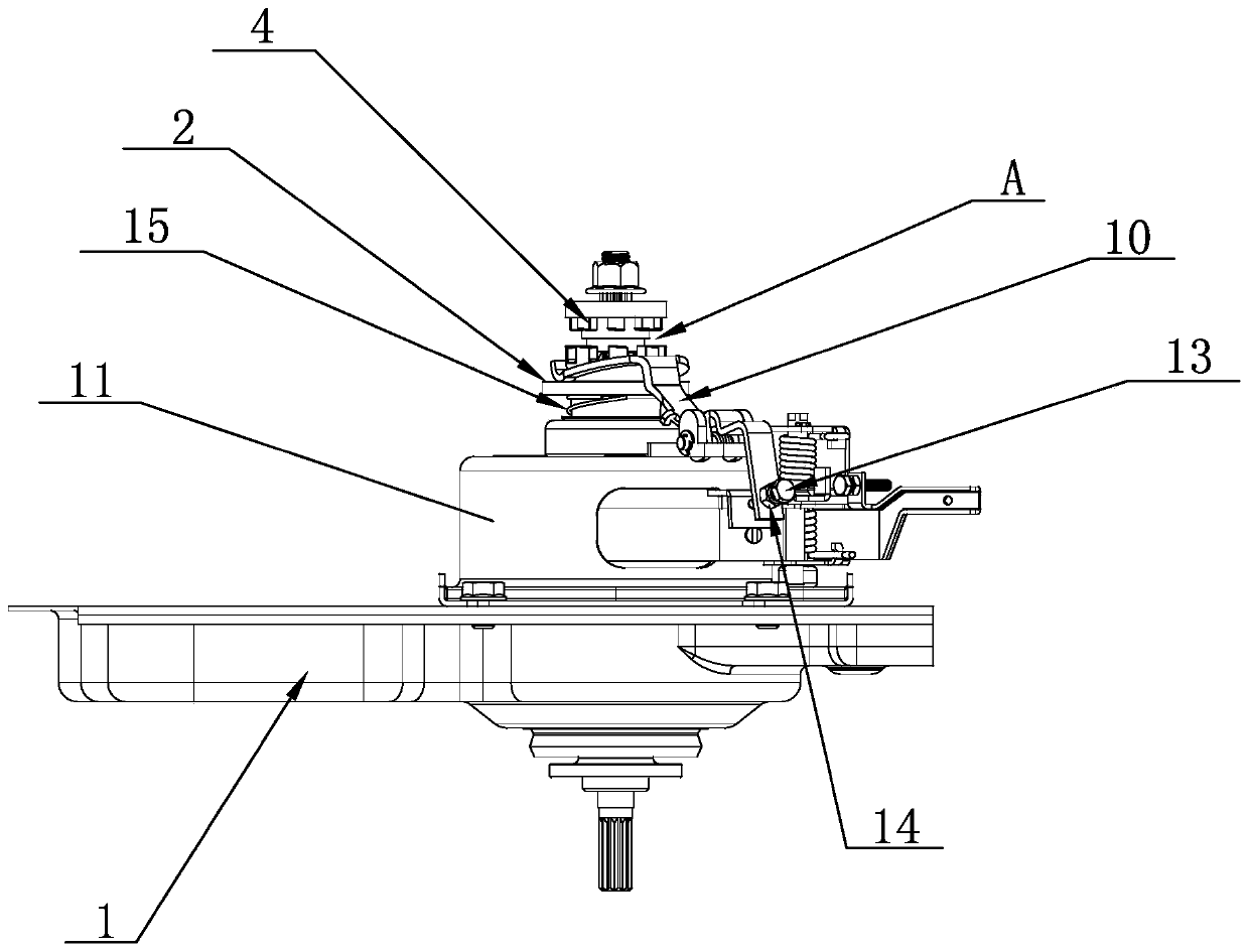
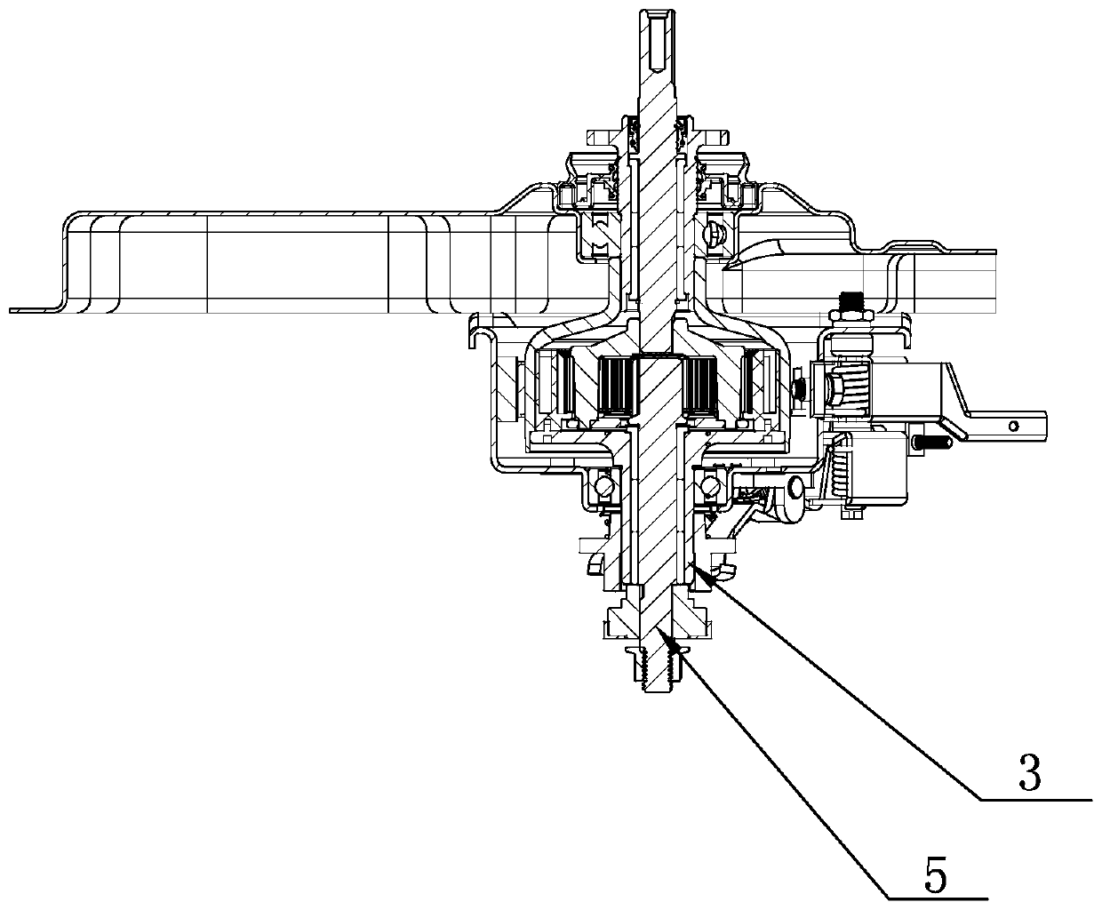
[0021] see Figure 1 to Figure 5 , a clutch device for a deceleration clutch disclosed in the present invention, comprising a lower housing 1, a coupling disc 2, a brake wheel...


PUM


Abstract

The invention discloses a clutch device of a speed reduction clutch. The device comprises a lower shell, a linkage disc, a brake axle, a torque transmission shaft sleeve, an input shaft and brake armpins. A shifting fork positioning block is fixedly arranged on the lower shell and provided with multiple pin holes, shifting fork linkage pins penetrate through the pin holes, shifting fork springs sleeve the shifting fork linkage pins, and a shifting fork is connected to each shifting fork spring. One end of the shifting fork is provided with a shifting fork push arm, the shifting fork push armssleeve the brake arm pins, and the shifting fork push arms are provided with shifting fork push arm torsional springs. One end of each shifting fork push arm is provided with a positioning face, theother end of each shifting fork push arm is provided with a contact plane, the portion, aligned with the corresponding contact plane, of each shifting fork is provided with a screw hole, a limit screwis in threaded connection with the interior of each screw hole, and the head of each limit screw abuts against the corresponding contact plane. According to the technical scheme, the clutch device isreasonable in structural design and simple in structure, the shifting forks and positioning discs do not easily deform, assembly is easy, the reject ratio of production can be lowered, the productionefficiency can be improved, and the practicability is good.

Description

technical field [0001] The invention relates to the technical field of clutches, in particular to a clutch device of a speed reduction clutch. Background technique [0002] The speed-reducing clutch of existing washing machine can be divided into two classes by clutch structure type: 1. ratchet, clutch clutch spring type clutch structure; However, most of the shift forks and positioning plates of the existing shift fork jaw clutch structure are made of plastic materials, and the plastic shift forks and positioning plates are prone to defects such as deformation after long-term use, and the assembly process is cumbersome and the production efficiency is low. [0003] In addition, during the production of the existing shift fork jaw-type clutch structure, because the shift fork and positioning plate are plastic parts, there are processing errors and deformation, and there is no adjustment device to adjust, the gap variation range of technical requirements is large, and the def...

Claims


Application Information

Patent Timeline
Patent Type & Authority Applications(China)
IPC IPC(8): F16D23/12F16D23/14D06F37/40
CPCD06F37/40F16D23/12F16D23/14F16D2023/141
Inventor 林华斌叶芳芳许益勇蔡泽豪
Owner ZHEJIANG SANXING MECHANICAL & ELECTRONICSAL STOCK
Why Eureka
Try Eureka